0.00
Problems that solves
High costs of routine operations
Insufficient risk management
Low speed of report generation
Unstructured data
Values
Support Decision Making
Reduce Production Timelines
Manage Risks
Improve Product Quality
Social Responsibility
Legion Simulator
Simulate People Movement and Test Space Performance to Deliver Fit-for-Purpose Infrastructure
About Product
About Product
Description
Simulation Software
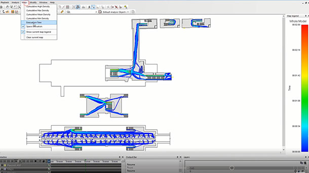
Generate simulations with predictive capacity across a wide range of scenarios and explore how pedestrians and crowds interact with infrastructure. Perform virtual experiments on the design and operation of a site and assess the impact of different levels of pedestrian demand. With sophisticated modeling, analysis, and presentation capabilities for projects ranging from airports to train stations to sports venues, LEGION Simulator helps enhance pedestrian flow and improve safety by allowing the users to test evacuation strategies at any point of the simulations. Scientifically Validated: Based on extensive scientific research of pedestrians’ behavior in real contexts. Algorithms are patented, and simulation results have been validated against empirical measurements and qualitative studies. Interoperable: Integrate with other applications to understand interaction among pedestrians and vehicles and individuals' reaction to temperature and other variables. Accurate Reporting: Export and report clear outputs via maps, graphs, and videos to accurately inform stakeholders about crowd density, evacuation, space utilization, social cost, and preferred paths over time.Capabilities
- Analyze Simulations
- Record and Playback Simulations
- Simulate Movement
- Visualize Simulations
Scheme of work
Competitive products
{"global":{"lastError":{},"locale":"de","locales":{"data":[{"id":"de","name":"Deutsch"},{"id":"en","name":"English"}],"loading":false,"error":false},"currency":{"id":49,"name":"EUR"},"currencies":{"data":[{"id":49,"name":"EUR"},{"id":124,"name":"RUB"},{"id":153,"name":"UAH"},{"id":155,"name":"USD"}],"loading":false,"error":false},"translations":{"product":{"reference-bonus":{"en":"Offer a reference bonus","ru":"Предложить бонус за референс","_type":"localeString"},"configurator":{"ru":"Конфигуратор","_type":"localeString","en":"Сonfigurator"},"i-sell-it":{"ru":"I sell it","_type":"localeString","en":"I sell it"},"i-use-it":{"ru":"I use it","_type":"localeString","en":"I use it"},"roi-calculator":{"ru":"ROI-калькулятор","_type":"localeString","en":"ROI-calculator"},"selling":{"_type":"localeString","en":"Selling","ru":"Продают"},"using":{"en":"Using","ru":"Используют","_type":"localeString"},"show-more-button":{"ru":"Показать еще","_type":"localeString","en":"Show more"},"hide-button":{"ru":"Скрыть","_type":"localeString","en":"Hide"},"supplier-popover":{"en":"supplier","ru":"поставщик","_type":"localeString"},"implementation-popover":{"ru":"внедрение","_type":"localeString","en":"deployment"},"manufacturer-popover":{"en":"manufacturer","ru":"производитель","_type":"localeString"},"short-description":{"en":"Pitch","ru":"Краткое описание","_type":"localeString"},"i-use-it-popover":{"en":"Make your introduction and get a bonus from ROI4CIO or the supplier.","ru":"Внесите свое внедрение и получите бонус от ROI4CIO или поставщика.","_type":"localeString"},"details":{"ru":"Детальнее","_type":"localeString","en":"Details"},"description":{"ru":"Описание","_type":"localeString","en":"Description"},"product-features":{"ru":"Особенности продукта","_type":"localeString","en":"Product features"},"categories":{"en":"Categories","ru":"Категории","_type":"localeString"},"solutions":{"en":" Problems that solves","ru":"Проблемы которые решает","_type":"localeString"},"values":{"en":"Values","ru":"Ценности","_type":"localeString"},"сomparison-matrix":{"ru":"Матрица сравнения","_type":"localeString","en":"Comparison matrix"},"testing":{"ru":"Тестирование","_type":"localeString","en":"Testing"},"compare":{"_type":"localeString","en":"Compare with competitors","ru":"Сравнить с конкурентами"},"characteristics":{"ru":"Характеристики","_type":"localeString","en":" Characteristics"},"transaction-features":{"en":"Transaction Features","ru":"Особенности сделки","_type":"localeString"},"average-discount":{"ru":"Средняя скидка партнера","_type":"localeString","en":"Partner average discount"},"deal-protection":{"en":"Deal protection","ru":"Защита сделки","_type":"localeString"},"average-deal":{"_type":"localeString","en":"Average deal size","ru":"Средний размер сделки"},"average-time":{"ru":"Средний срок закрытия сделки","_type":"localeString","en":"Average deal closing time"},"login":{"en":"Login","ru":"Войти","_type":"localeString"},"register":{"_type":"localeString","en":"Register","ru":"Зарегистрироваться"},"to-know-more":{"_type":"localeString","en":"To know more","ru":"Чтобы узнать больше"},"scheme":{"ru":"Схема работы","_type":"localeString","en":" Scheme of work"},"competitive-products":{"_type":"localeString","en":" Competitive products","ru":"Конкурентные продукты"},"implementations-with-product":{"ru":"Внедрения с этим продуктом","_type":"localeString","en":"Deployments with this product"},"user-features":{"ru":"Особенности пользователей","_type":"localeString","en":"User features"},"job-roles":{"ru":"Роли заинтересованных сотрудников","_type":"localeString","en":" Roles of Interested Employees"},"organizational-features":{"ru":"Организационные особенности","_type":"localeString","en":"Organizational Features"},"calculate-price":{"_type":"localeString","en":" Calculate product price","ru":"Рассчитать цену продукта"},"selling-stories":{"_type":"localeString","en":" Selling stories","ru":"Продающие истории"},"materials":{"ru":"Материалы","_type":"localeString","en":"Materials"},"about-product":{"ru":"О продукте","_type":"localeString","en":"About Product"},"or":{"en":"or","ru":"или","_type":"localeString"},"program-sends-data":{"en":"Program Sends Data","_type":"localeString"},"calculate-roi":{"ru":"Рассчитать ROI продукта","_type":"localeString","en":"Calculate Product ROI"},"complementary-categories":{"ru":"Схожие категории","_type":"localeString","en":"Complementary Categories"},"program-receives-data":{"_type":"localeString","en":"Program Receives Data"},"rebate":{"en":"Bonus","ru":"Бонус","_type":"localeString"},"rebate-for-poc":{"en":"Bonus 4 POC","ru":"Бонус 4 POC","_type":"localeString"},"configurator-content":{"_type":"localeString","en":"Calculate price for this product here","ru":"Рассчитайте стоимость продукта"},"configurator-link":{"ru":"тут","_type":"localeString","en":"here"},"vendor-popover":{"en":"vendor","ru":"производитель","_type":"localeString"},"user-popover":{"ru":"пользователь","_type":"localeString","en":"user"},"select-for-presentation":{"_type":"localeString","en":"select product for presentation","ru":"выбрать продукт для презентации"},"auth-message":{"ru":"Вам нужно зарегистрироваться или войти.","_type":"localeString","en":"You have to register or login."},"add-to-comparison":{"ru":"Добавить в сравнение","_type":"localeString","en":"Add to comparison"},"added-to-comparison":{"en":"Added to comparison","ru":"Добавлено в сравнения","_type":"localeString"},"roi-calculator-content":{"_type":"localeString","en":"Calculate ROI for this product here","ru":"Рассчитайте ROI для данного продукта"},"not-yet-converted":{"ru":"Данные модерируются и вскоре будут опубликованы. Попробуйте повторить переход через некоторое время.","_type":"localeString","en":"Data is moderated and will be published soon. Please, try again later."},"videos":{"ru":"Видео","_type":"localeString","en":"Videos"},"vendor-verified":{"en":"Vendor verified","ru":"Подтверждено производителем","_type":"localeString"},"event-schedule":{"ru":"Расписание событий","_type":"localeString","en":"Events schedule"},"scheduling-tip":{"ru":"Выберите удобную дату и время и зарегистрируйтесь на ивент.","_type":"localeString","en":"Please, сhoose a convenient date and time and register for the event."},"register-to-schedule":{"ru":"Для того чтобы зарегистрироваться на ивент пожалуйста авторизируйтесь или зарегистрируйтесь на сайт.","_type":"localeString","en":"To register for the event please log in or register on the site."},"comparison-matrix":{"en":"Comparison matrix","ru":"Матрица сравнений","_type":"localeString"},"compare-with-competitive":{"en":" Compare with competitive","ru":"Сравнить с конкурентными","_type":"localeString"},"avg-deal-closing-unit":{"ru":"месяцев","_type":"localeString","en":"months"},"under-construction":{"en":"Current feature is still developing to become even more useful for you.","ru":"Данная услуга всё ещё находится в разработке.","_type":"localeString"},"product-presentation":{"en":"Product presentation","ru":"Презентация продукта","_type":"localeString"},"go-to-comparison-table":{"_type":"localeString","en":" Go to comparison table","ru":"Перейти к таблице сравнения"},"see-product-details":{"_type":"localeString","en":"See Details","ru":"Детали"}},"header":{"help":{"_type":"localeString","en":"Help","de":"Hilfe","ru":"Помощь"},"how":{"en":"How does it works","de":"Wie funktioniert es","ru":"Как это работает","_type":"localeString"},"login":{"ru":"Вход","_type":"localeString","en":"Log in","de":"Einloggen"},"logout":{"en":"Sign out","ru":"Выйти","_type":"localeString"},"faq":{"_type":"localeString","en":"FAQ","de":"FAQ","ru":"FAQ"},"references":{"_type":"localeString","en":"Requests","de":"References","ru":"Мои запросы"},"solutions":{"ru":"Возможности","_type":"localeString","en":"Solutions"},"find-it-product":{"en":"Selection and comparison of IT product","ru":"Подбор и сравнение ИТ продукта","_type":"localeString"},"autoconfigurator":{"ru":"Калькулятор цены","_type":"localeString","en":" Price calculator"},"comparison-matrix":{"en":"Comparison Matrix","ru":"Матрица сравнения","_type":"localeString"},"roi-calculators":{"ru":"ROI калькуляторы","_type":"localeString","en":"ROI calculators"},"b4r":{"_type":"localeString","en":"Bonus for reference","ru":"Бонус за референс"},"business-booster":{"ru":"Развитие бизнеса","_type":"localeString","en":"Business boosting"},"catalogs":{"ru":"Каталоги","_type":"localeString","en":"Catalogs"},"products":{"ru":"Продукты","_type":"localeString","en":"Products"},"implementations":{"ru":"Внедрения","_type":"localeString","en":"Deployments"},"companies":{"ru":"Компании","_type":"localeString","en":"Companies"},"categories":{"en":"Categories","ru":"Категории","_type":"localeString"},"for-suppliers":{"ru":"Поставщикам","_type":"localeString","en":"For suppliers"},"blog":{"_type":"localeString","en":"Blog","ru":"Блог"},"agreements":{"ru":"Сделки","_type":"localeString","en":"Deals"},"my-account":{"ru":"Мой кабинет","_type":"localeString","en":"My account"},"register":{"ru":"Зарегистрироваться","_type":"localeString","en":"Register"},"comparison-deletion":{"ru":"Удаление","_type":"localeString","en":"Deletion"},"comparison-confirm":{"_type":"localeString","en":"Are you sure you want to delete","ru":"Подтвердите удаление"},"search-placeholder":{"_type":"localeString","en":"Enter your search term","ru":"Введите поисковый запрос"},"my-profile":{"_type":"localeString","en":"My profile","ru":"Мои данные"},"about":{"_type":"localeString","en":"About Us"},"it_catalogs":{"_type":"localeString","en":"IT catalogs"},"roi4presenter":{"_type":"localeString","en":"Roi4Presenter"},"roi4webinar":{"_type":"localeString","en":"Pitch Avatar"},"sub_it_catalogs":{"en":"Find IT product","_type":"localeString"},"sub_b4reference":{"_type":"localeString","en":"Get reference from user"},"sub_roi4presenter":{"_type":"localeString","en":"Make online presentations"},"sub_roi4webinar":{"_type":"localeString","en":"Create an avatar for the event"},"catalogs_new":{"en":"Products","_type":"localeString"},"b4reference":{"_type":"localeString","en":"Bonus4Reference"},"it_our_it_catalogs":{"en":"Our IT Catalogs","_type":"localeString"},"it_products":{"_type":"localeString","en":"Find and compare IT products"},"it_implementations":{"_type":"localeString","en":"Learn implementation reviews"},"it_companies":{"_type":"localeString","en":"Find vendor and company-supplier"},"it_categories":{"_type":"localeString","en":"Explore IT products by category"},"it_our_products":{"_type":"localeString","en":"Our Products"},"it_it_catalogs":{"_type":"localeString","en":"IT catalogs"}},"footer":{"copyright":{"_type":"localeString","en":"All rights reserved","de":"Alle rechte vorbehalten","ru":"Все права защищены"},"company":{"en":"My Company","de":"Über die Firma","ru":"О компании","_type":"localeString"},"about":{"ru":"О нас","_type":"localeString","en":"About us","de":"Über uns"},"infocenter":{"ru":"Инфоцентр","_type":"localeString","en":"Infocenter","de":"Infocenter"},"tariffs":{"en":"Subscriptions","de":"Tarife","ru":"Тарифы","_type":"localeString"},"contact":{"en":"Contact us","de":"Kontaktiere uns","ru":"Связаться с нами","_type":"localeString"},"marketplace":{"ru":"Marketplace","_type":"localeString","en":"Marketplace","de":"Marketplace"},"products":{"_type":"localeString","en":"Products","de":"Produkte","ru":"Продукты"},"compare":{"ru":"Подобрать и сравнить","_type":"localeString","en":"Pick and compare","de":"Wähle und vergleiche"},"calculate":{"de":"Kosten berechnen","ru":"Расчитать стоимость","_type":"localeString","en":"Calculate the cost"},"get_bonus":{"de":"Holen Sie sich einen Rabatt","ru":"Бонус за референс","_type":"localeString","en":"Bonus for reference"},"salestools":{"de":"Salestools","ru":"Salestools","_type":"localeString","en":"Salestools"},"automatization":{"de":"Abwicklungsautomatisierung","ru":"Автоматизация расчетов","_type":"localeString","en":"Settlement Automation"},"roi_calcs":{"_type":"localeString","en":"ROI calculators","de":"ROI-Rechner","ru":"ROI калькуляторы"},"matrix":{"en":"Comparison matrix","de":"Vergleichsmatrix","ru":"Матрица сравнения","_type":"localeString"},"b4r":{"_type":"localeString","en":"Rebate 4 Reference","de":"Rebate 4 Reference","ru":"Rebate 4 Reference"},"our_social":{"ru":"Наши социальные сети","_type":"localeString","en":"Our social networks","de":"Unsere sozialen Netzwerke"},"subscribe":{"de":"Melden Sie sich für den Newsletter an","ru":"Подпишитесь на рассылку","_type":"localeString","en":"Subscribe to newsletter"},"subscribe_info":{"ru":"и узнавайте первыми об акциях, новых возможностях и свежих обзорах софта","_type":"localeString","en":"and be the first to know about promotions, new features and recent software reviews"},"policy":{"ru":"Политика конфиденциальности","_type":"localeString","en":"Privacy Policy"},"user_agreement":{"ru":"Пользовательское соглашение ","_type":"localeString","en":"Agreement"},"solutions":{"_type":"localeString","en":"Solutions","ru":"Возможности"},"find":{"_type":"localeString","en":"Selection and comparison of IT product","ru":"Подбор и сравнение ИТ продукта"},"quote":{"ru":"Калькулятор цены","_type":"localeString","en":"Price calculator"},"boosting":{"_type":"localeString","en":"Business boosting","ru":"Развитие бизнеса"},"4vendors":{"ru":"поставщикам","_type":"localeString","en":"4 vendors"},"blog":{"en":"blog","ru":"блог","_type":"localeString"},"pay4content":{"en":"we pay for content","ru":"платим за контент","_type":"localeString"},"categories":{"en":"categories","ru":"категории","_type":"localeString"},"showForm":{"en":"Show form","ru":"Показать форму","_type":"localeString"},"subscribe__title":{"ru":"Раз в месяц мы отправляем дайджест актуальных новостей ИТ мира!","_type":"localeString","en":"We send a digest of actual news from the IT world once in a month!"},"subscribe__email-label":{"ru":"Email","_type":"localeString","en":"Email"},"subscribe__name-label":{"ru":"Имя","_type":"localeString","en":"Name"},"subscribe__required-message":{"en":"This field is required","ru":"Это поле обязательное","_type":"localeString"},"subscribe__notify-label":{"ru":"Да, пожалуйста уведомляйте меня о новостях, событиях и предложениях","_type":"localeString","en":"Yes, please, notify me about news, events and propositions"},"subscribe__agree-label":{"en":"By subscribing to the newsletter, you agree to the %TERMS% and %POLICY% and agree to the use of cookies and the transfer of your personal data","ru":"Подписываясь на рассылку, вы соглашаетесь с %TERMS% и %POLICY% и даете согласие на использование файлов cookie и передачу своих персональных данных*","_type":"localeString"},"subscribe__submit-label":{"ru":"Подписаться","_type":"localeString","en":"Subscribe"},"subscribe__email-message":{"ru":"Пожалуйста, введите корректный адрес электронной почты","_type":"localeString","en":"Please, enter the valid email"},"subscribe__email-placeholder":{"ru":"username@gmail.com","_type":"localeString","en":"username@gmail.com"},"subscribe__name-placeholder":{"_type":"localeString","en":"Last, first name","ru":"Имя Фамилия"},"subscribe__success":{"ru":"Вы успешно подписаны на рассылку. Проверьте свой почтовый ящик.","_type":"localeString","en":"You are successfully subscribed! Check you mailbox."},"subscribe__error":{"_type":"localeString","en":"Subscription is unsuccessful. Please, try again later.","ru":"Не удалось оформить подписку. Пожалуйста, попробуйте позднее."},"roi4presenter":{"_type":"localeString","en":"Roi4Presenter","de":"roi4presenter","ru":"roi4presenter"},"it_catalogs":{"_type":"localeString","en":"IT catalogs"},"roi4webinar":{"_type":"localeString","en":"Pitch Avatar"},"b4reference":{"en":"Bonus4Reference","_type":"localeString"}},"breadcrumbs":{"home":{"en":"Home","ru":"Главная","_type":"localeString"},"companies":{"ru":"Компании","_type":"localeString","en":"Companies"},"products":{"ru":"Продукты","_type":"localeString","en":"Products"},"implementations":{"ru":"Внедрения","_type":"localeString","en":"Deployments"},"login":{"_type":"localeString","en":"Login","ru":"Вход"},"registration":{"ru":"Регистрация","_type":"localeString","en":"Registration"},"b2b-platform":{"_type":"localeString","en":"B2B platform for IT buyers, vendors and suppliers","ru":"Портал для покупателей, поставщиков и производителей ИТ"}},"comment-form":{"title":{"ru":"Оставить комментарий","_type":"localeString","en":"Leave comment"},"firstname":{"_type":"localeString","en":"First name","ru":"Имя"},"lastname":{"en":"Last name","ru":"Фамилия","_type":"localeString"},"company":{"_type":"localeString","en":"Company name","ru":"Компания"},"position":{"_type":"localeString","en":"Position","ru":"Должность"},"actual-cost":{"en":"Actual cost","ru":"Фактическая стоимость","_type":"localeString"},"received-roi":{"en":"Received ROI","ru":"Полученный ROI","_type":"localeString"},"saving-type":{"ru":"Тип экономии","_type":"localeString","en":"Saving type"},"comment":{"ru":"Комментарий","_type":"localeString","en":"Comment"},"your-rate":{"ru":"Ваша оценка","_type":"localeString","en":"Your rate"},"i-agree":{"en":"I agree","ru":"Я согласен","_type":"localeString"},"terms-of-use":{"en":"With user agreement and privacy policy","ru":"С пользовательским соглашением и политикой конфиденциальности","_type":"localeString"},"send":{"_type":"localeString","en":"Send","ru":"Отправить"},"required-message":{"ru":"{NAME} - это обязательное поле","_type":"localeString","en":"{NAME} is required filed"}},"maintenance":{"title":{"_type":"localeString","en":"Site under maintenance","ru":"На сайте проводятся технические работы"},"message":{"ru":"Спасибо за ваше понимание","_type":"localeString","en":"Thank you for your understanding"}}},"translationsStatus":{"product":"success"},"sections":{},"sectionsStatus":{},"pageMetaData":{"product":{"translatable_meta":[{"name":"og:title","translations":{"_type":"localeString","en":"Example product","ru":"Конкретный продукт"}},{"translations":{"en":"Description for one product","ru":"Описание для конкретного продукта","_type":"localeString"},"name":"og:description"},{"name":"title","translations":{"ru":"Продукт","_type":"localeString","en":"Product"}},{"name":"description","translations":{"_type":"localeString","en":"Product description","ru":"Описание продукта"}},{"translations":{"ru":"Ключевые слова продукта","_type":"localeString","en":"Product keywords"},"name":"keywords"}],"title":{"en":"ROI4CIO: Product","ru":"ROI4CIO: Продукт","_type":"localeString"},"meta":[{"content":"website","name":"og:type"},{"name":"og:image","content":"https://roi4cio.com/fileadmin/templates/roi4cio/image/roi4cio-logobig.jpg"}]}},"pageMetaDataStatus":{"product":"success"},"subscribeInProgress":false,"subscribeError":false},"auth":{"inProgress":false,"error":false,"checked":true,"initialized":false,"user":{},"role":null,"expires":null},"products":{"productsByAlias":{"legion-simulator":{"id":6642,"logoURL":"https://old.roi4cio.com/fileadmin/user_upload/bentley_systems.png","logo":true,"schemeURL":"https://old.roi4cio.com/fileadmin/user_upload/LEGION_scheme.jpg","scheme":true,"title":"Legion Simulator","vendorVerified":1,"rating":"0.00","implementationsCount":0,"suppliersCount":0,"supplierPartnersCount":1,"alias":"legion-simulator","companyTitle":"Bentley Systems","companyTypes":["vendor"],"companyId":2776,"companyAlias":"bentley-systems","description":"<h1 class=\"align-center\">Simulation Software </h1>\r\n<span style=\"font-style: italic; \"><span style=\"font-weight: bold; \">Generate simulations with predictive capacity across a wide range of scenarios and explore how pedestrians and crowds interact with infrastructure.</span></span>\r\nPerform virtual experiments on the design and operation of a site and assess the impact of different levels of pedestrian demand. With sophisticated modeling, analysis, and presentation capabilities for projects ranging from airports to train stations to sports venues, LEGION Simulator helps enhance pedestrian flow and improve safety by allowing the users to test evacuation strategies at any point of the simulations.\r\n<span style=\"font-weight: bold; \">Scientifically Validated: </span>Based on extensive scientific research of pedestrians’ behavior in real contexts. Algorithms are patented, and simulation results have been validated against empirical measurements and qualitative studies.\r\n<span style=\"font-weight: bold; \">Interoperable:</span> Integrate with other applications to understand interaction among pedestrians and vehicles and individuals' reaction to temperature and other variables.\r\n<span style=\"font-weight: bold; \">Accurate Reporting:</span> Export and report clear outputs via maps, graphs, and videos to accurately inform stakeholders about crowd density, evacuation, space utilization, social cost, and preferred paths over time. \r\n<h1 class=\"align-center\">Capabilities</h1>\r\n<ul><li><span style=\"font-weight: bold;\">Analyze Simulations</span></li></ul>\r\nSet up and run user-defined analyzes and generate rich outputs based on a variety of metrics.\r\n<ul><li><span style=\"font-weight: bold;\">Record and Playback Simulations</span></li></ul>\r\nRecord and play back parts of a simulation, or run a new simulation.\r\n<ul><li><span style=\"font-weight: bold;\">Simulate Movement</span></li></ul>\r\nMimic all aspects of an individual’s movement including personal preferences, surrounding awareness, spatial restrictions, and perception of behaviors.\r\n<ul><li><span style=\"font-weight: bold;\">Visualize Simulations</span></li></ul>\r\nView simulations in various speeds, zoom in/out, pause/restart, and export for analysis. Simplified and automated analyzes speed the analysis stage of a project to reduce risk.<br /><br />\r\n<div id=\"CarouselDescription\" class=\"carousel-description\">\r\n<div class=\"jwplayer-slider\" style=\"visibility: visible; \"><div class=\"flex-viewport\" style=\"overflow: hidden; position: relative; \"><ul class=\"slides\" style=\"width: 1000%; transition-duration: 0s; transform: translate3d(0px, 0px, 0px); \"><li class=\"active\" style=\"width: 159.667px; float: left; display: block; \"> </li></ul>\r\n\r\n\r\n","shortDescription":"Simulate People Movement and Test Space Performance to Deliver Fit-for-Purpose Infrastructure ","type":"Software","isRoiCalculatorAvaliable":false,"isConfiguratorAvaliable":false,"bonus":100,"usingCount":0,"sellingCount":0,"discontinued":0,"rebateForPoc":0,"rebate":0,"seo":{"title":"Legion Simulator","keywords":"","description":"<h1 class=\"align-center\">Simulation Software </h1>\r\n<span style=\"font-style: italic; \"><span style=\"font-weight: bold; \">Generate simulations with predictive capacity across a wide range of scenarios and explore how pedestrians and crowds interact with inf","og:title":"Legion Simulator","og:description":"<h1 class=\"align-center\">Simulation Software </h1>\r\n<span style=\"font-style: italic; \"><span style=\"font-weight: bold; \">Generate simulations with predictive capacity across a wide range of scenarios and explore how pedestrians and crowds interact with inf","og:image":"https://old.roi4cio.com/fileadmin/user_upload/bentley_systems.png"},"eventUrl":"","translationId":6642,"dealDetails":null,"roi":null,"price":null,"bonusForReference":null,"templateData":[],"testingArea":"","categories":[{"id":780,"title":"CAD for architecture and construction - Computer-Aided Design","alias":"cad-for-architecture-and-construction-computer-aided-design","description":"Computer-aided design (CAD) is the use of computers (or workstations) to aid in the creation, modification, analysis or optimization of a design. CAD software is used to increase the productivity of the designer, improve the quality of design, improve communications through documentation and to create a database for manufacturing. CAD output is often in the form of electronic files for print, machining or other manufacturing operations. The term CADD (for Computer Aided Design and Drafting) is also used.\r\nCAD may be used to design curves and figures in two-dimensional (2D) space or curves, surfaces and solids in three-dimensional (3D) space.\r\nCAD is an important industrial art extensively used in many applications, including architectural design, prosthetics and many more.\r\nSoftware for architecture - systems designed specifically for architects, whose tools allow you to build drawings and models from familiar objects (walls, columns, floors, etc.), to design buildings and facilities for industrial and civil construction. These programs have the tools to build three-dimensional models and obtain all the necessary working documentation and support modern technology of information modeling of buildings.<br /><br />","materialsDescription":"<h1 class=\"align-center\"> <span style=\"font-weight: normal;\">What is a CAD drafter or CAD Designer?</span></h1>\r\nEverything around us that is manufactured begins with an idea in a written plan. When these plans require illustrations or drawings to convey meaning, a CAD drafter is needed to prepare these ideas in graphic forms of communication. Drafters translate ideas and rough sketches of other professionals, such as architects and engineers, into scaled detail (or working) drawings. A CAD designer often prepares the plans and rough sketches for an architect or engineer. The designer has more education and thus more responsibility than the drafter but less than an architect or engineer.\r\n<h1 class=\"align-center\"><span style=\"font-weight: normal;\">What software do architects use?</span></h1>\r\n<p class=\"align-left\">Before computer-aided design software, architects relied solely on hand drawings and handmade architecture models to communicate their designs. With the evolution of technology and the architecture industry, architectural drafting software has changed the way architects plan and design buildings. Implementing 2D and 3D architecture software allows designers to draft at greater speed, test ideas and determine consistent project workflows. Advancements in rendering software provide architects and their clients with the ability to visually experience designs before a project is realized.</p>\r\n<h1 class=\"align-center\"><span style=\"font-weight: normal;\">Is CAD 2D or 3D?</span></h1>\r\n<p class=\"align-left\">A common misconception surrounding CAD is that it is a 3D architecture software modeling tool only. However, CAD can be used as a 2D drawing tool as well. Construction designers might use a CAD tool that only works in 2D while architects might work in a 3D software architecture tools that has a 2D converter. It is highly dependent upon the actual platform used. This can be convenient because a company might only use a 2D tool and can pay for that tool alone. However, as construction centers around 3D modeling software for architecture and informational models, it will be harder for companies who only to use a 2D tool.</p>\r\n<h1 class=\"align-center\"><span style=\"font-weight: normal;\">What is CAD used for in construction?</span></h1>\r\n<p class=\"align-left\">There are a lot of uses for CAD in construction. Subcontractor’s designers can take the drawings made by the architect and add in additional necessary details to ensure constructability. From there they have a plan that they can work off of and check their work against. Companies have already done this to a degree of success. Some companies were able to use a combination of drones and 3D models to notice issues with the construction. Specifically, a company can overlay their live drone footage with the model. They could note that the foundation would be off and make corrections.</p>\r\n<p class=\"align-left\">Architecture planning software benefits contractors because the drawings and plans can be easily stored in the cloud. This allows for contractors to use their plans at any location. Also, if they are included in a shared file for the project, they can easily see changes to the plans. So, a subcontractor could quickly determine which changes were made, by who, and how it will impact construction.</p>\r\n<p class=\"align-left\">Another benefit of professional architecture software is it is more accurate than manual drawings. It’s easier for construction design software than it is when it’s manual. And it’s easier for subcontractors to add details than it is in manual drawings.</p>\r\n<h1 class=\"align-center\"><span style=\"font-weight: normal;\">What architects’ tools have been transformed by technology?</span></h1>\r\nWorking methods that previously resulted in only the documentation of an idea are now moving toward the realization of a full virtual copy of a building and all its complex components before a single nail is hammered. As such, architects’ tools that used to be physical, like pens and pencils, are now mere basics in a virtual toolbox with capabilities an analog architect couldn’t even fathom. The breakneck pace of this change is good reason to reflect on the history of these architect software virtual tools by comparing them to their physical forebears.\r\n\r\n<ul><li><span style=\"font-weight: bold;\">Drafting Arm vs. Dynamic Input. </span>Appearing like an alien appendage affixed to a drawing board, a drafting arm originally consolidated a variety of tasks completed with separate rulers, straightedges and protractors into a single versatile tool. AutoCAD’s crosshair reticle, for example, once relied on manual input with compass-style designations before it featured point-and-click functionality with real-time metrics following it around the screen.</li></ul>\r\n\r\n<ul><li><span style=\"font-weight: bold;\">Tape Measure vs. Surveying App.</span> Documenting an existing building in order to plan its transformation is likely one of the most frequent tasks architects complete. Until recently, the only way to correctly do this was by hand, with a tape measure, pen and paper. Since the advent of infrared scanners, depth-sensing cameras and software that can communicate with them, the time-intensive process of surveying an existing space has been cut to a fraction of what it once was.</li></ul>\r\n\r\n<ul><li><span style=\"font-weight: bold;\">Drafting Template vs. Premade 3-D Models.</span> In the days of hand-drafting, adding furniture to a drawing meant choosing an appropriately scaled object from a stencil and tracing it. Today’s sophisticated equivalent that architecture software programs offer allows an infinite number of premade models to be brought into a wide range of design software with a single click. Despite technological advances in this practice, the old method may actually be advantageous due to its reliance on abstraction because choosing realistically detailed furnishings for an early design scheme often prompts cosmetic decisions long before they need to be made.</li></ul>\r\n\r\n<ul><li><span style=\"font-weight: bold;\">Electric Eraser vs. Undo.</span> The most simple, and, for this reason, the most underappreciated, transformation an architect’s tools have undergone between physical and virtual methods is the ease with which one can now reverse the work they’ve done. Allowing what essentially amounts to time travel, the Undo function is universal to almost all software programs and as such is often taken for granted. Prior to this wonderful invention, the savviest architects wielded handheld electric erasers allowing them to salvage large drawing sets in the event of a drafting mistake or last-minute design change.</li></ul>\r\n\r\n<ul><li><span style=\"font-weight: bold;\">Blueprint Machine vs. Inkjet Plotter. </span>If you hang around an architecture firm long enough, you might hear older designers talk about using a blueprint machine. Originally the premier method for producing copies of drawings, blueprint machines involved rolling an original drawing through a chemical mixture that reproduced the image on a special type of paper. For some time now, digital plotters have removed manual labor from the equation, being fed information directly from a virtual drawing file.</li></ul>\r\n\r\n<ul><li><span style=\"font-weight: bold;\">Digitizer Tablet vs. Touchscreen Workstation.</span> Early iterations of digital drafting were often paired with a digitizer: a special keyboard that could choose commands or be directly drawn on. Software used in architecture eventually got better at incorporating a keyboard and mouse, but nowadays the tide might be turning back to a hands-on approach as devices like Microsoft’s Surface Studio are pushing an interface with touch-heavy tools just for architects. Though currently limited to apps for sketching and drawing review, the way architects work could be changed forever if a large influential company like Autodesk or Graphisoft were to fully embrace touchscreen capabilities.</li></ul>\r\n\r\n<p class=\"align-left\"><br /><br /> <br /><br /><br /></p>","iconURL":"https://old.roi4cio.com/fileadmin/user_upload/icon_CAD.png"},{"id":57,"title":"Engineering Applications","alias":"engineering-applications","description":"Specific segmentations of <span style=\"font-weight: bold;\">Engineering Applications</span> include software packages, such as 2D CAD, 3D CAD, engineering analysis, project software and services, collaborative engineering software, and asset information management. These tools are used not only for asset creation but also to manage data and information throughout the lifecycle of physical assets in both infrastructure and industry. Application of optimization techniques in engineering provides as-built information to owners for operations and maintenance requirements, as well as a document for any modifications to the facility.<span style=\"font-weight: bold; \"></span>\r\n<span style=\"font-weight: bold; \">Computer-aided design (CAD)</span> is the use of computers (or workstations) to aid in the creation, modification, analysis, or optimization of a design. CAD software is used to increase the productivity of the designer, improve the quality of design, improve communications through documentation, and to create a database for manufacturing. Computer engineering and intelligent systems output is often in the form of electronic files for print, machining, or other manufacturing operations. \r\nIts use in designing electronic systems is known as electronic design automation (EDA). Application of CAD in mechanical engineering is known as mechanical design automation (MDA) or computer-aided drafting (CAD), which includes the process of creating a technical drawing with the use of computer software.\r\nCAD software for mechanical design uses either vector-based graphics to depict the objects of traditional drafting, or may also produce raster graphics showing the overall appearance of designed objects. However, it involves more than just shapes. As in the manual drafting of technical and engineering drawings, the output of CAD must convey information, such as materials, processes, dimensions, and tolerances, according to application-specific conventions.\r\nCAD is an important industrial art extensively used in many engineering applications, including automotive, shipbuilding, and aerospace industries, industrial and architectural design, electrical engineering app, prosthetics, environmental engineering applications, and many more. \r\nEngineering apps and software are: 2D layout and CAD software, 3D design and visualization systems, Pre-engineering and FEED applications, Engineering information management systems, Asset lifecycle information management systems, Asset performance management systems, P&ID and piping layout design, 3D laser scanning and point cloud modeling, 3D augmented reality simulation systems, 3D virtual reality simulation based on other technologies (photometry, etc.), 3D virtual simulation for operator training, Electrical Engineering applications and HVAC design, Engineering analysis tools, Civil engineering design packages, Fabrication and construction management systems, Software implementation services, Software maintenance & support services, Software as a service including deployment (Cloud, subscription, etc.), Collaborative software for engineering workflows, Associated databases and interfaces.","materialsDescription":"<h1 class=\"align-center\">2D and 3D CAD software</h1>\r\n<p class=\"align-left\">General-purpose CAD software includes a wide range of 2D and 3D software. Before delving into the more specific types of CAD software, it’s important to understand the difference between 2D and 3D CAD and the various industries that leverage them.</p>\r\n<p class=\"align-left\">2D CAD software offers a platform to design in two dimensions. Since 2D CAD does not allow for the creation of perspectives or scale, it is often used for drawing, sketching and drafting conceptual designs. 2D CAD is often used for floor plan development, building permit drawing and building inspection planning. Since it is mainly used as a tool for conceptual design, it is also a great starting point for most 3D designs. This gives users a basic overview of dimension and scale before they move on to 3D design. 2D CAD typically runs at a significantly lower price since it does not provide the same scale of tools and breadth of features.</p>\r\n<p class=\"align-left\">3D CAD provides a platform for designing 3D objects. The main feature of this type of CAD software is 3D solid modeling. This lets designers create objects with length, width and height, allowing more accurate scaling and visualization. With this feature, users can push and pull surfaces and manipulate designs to adjust measurements. Once the 3D design is to your liking, you can transfer it to a 3D rendering software and place the designs in fully realized 3D landscapes.</p>\r\n<h1 class=\"align-center\">BIM software</h1>\r\n<p class=\"align-left\">One of the more specific types of 3D CAD software is building information modeling software, also known as BIM software. BIM software is intended to aid in the design and construction of buildings specifically. BIM software provides users with the ability to break down building parts and see how they fit into a single finalized structure. Users can isolate walls, columns, windows, doors, etc., and alter the design. Engineers, architect, and manufacturers are just some of the professionals that use BIM software on a regular basis.</p>\r\n<h1 class=\"align-center\">Civil engineering design software</h1>\r\n<p class=\"align-left\">Civil engineering design software allows users to design 3D models of municipal buildings and structures. This includes tools for railway modeling, highway design and city infrastructure planning. Similar to BIM, civil engineering design software helps in every stage of the design process by breaking it down to drafting, designing and visualizing the final product. Best app for civil engineering also helps designers determine building costs. Civil engineering design software is perfect for engineers working in public and civil departments including transportation, structural and geotech.</p>\r\n<h1 class=\"align-center\">3D printing software</h1>\r\n<p class=\"align-left\">3D printing software facilitates the printing of real-life 3D objects. When users design an object, it can bу translated into a 3D printing software. The software then relays instructions on how to print that design to an actual 3D printer. The 3D printing software sends instructions to just print out certain parts of an object, or it can print out the entirety of an object. Some CAD software doubles as 3D printing software so you can seamlessly produce actual 3D objects all from one platform. 3D printing software can be used by manufacturers and architects to build machine or building parts. This greatly reduces production costs, as manufacturers no longer need offsite locations for manufacturing. It also gives companies a rapid test drive to see how a product would look if it were mass produced.</p>","iconURL":"https://old.roi4cio.com/fileadmin/user_upload/Engineering_Applications.png"}],"characteristics":[],"concurentProducts":[{"id":6496,"logo":false,"scheme":false,"title":"Planbar","vendorVerified":0,"rating":"0.00","implementationsCount":0,"suppliersCount":0,"supplierPartnersCount":0,"alias":"planbar","companyTitle":"Precast Software Engineering","companyTypes":["supplier","vendor"],"companyId":8993,"companyAlias":"precast-software-engineering","description":"<span style=\"font-weight: bold;\">PLANBAR</span> offers an ideal and unique synthe-sis of model- and drawing-based work. \r\n<ul><li>Unique synthesis for model-based and drawing-based working, 3D as simple as 2D</li><li>Reliable data provision for production</li><li>Efficient design of highly complex components</li><li>Consistent data transfer</li><li>Automated creation of Shop Drawings</li></ul>\r\n<span style=\"font-weight: bold;\">The Elementplan</span> module solves the problem of automatically creating production documents from a model with geometry and reinforcement. This lets you work on the Shop Drawing and automatically adjusts the 3D model in the background, where PLANBAR automatically ensures that the model and drawing remain consistent.\r\nProduction documents will always be important. This is why we continue to focus on perfect, mostly automatic document preparation. \r\nThe design of reinforcement is a true highlight in PLANBAR and will optimally support you during the design and production processes of all types of precast parts. In this regard, PLANBAR automatically creates reinforcement in accordance with your specifications. Round steel, reinforcing mesh, mesh stirrup and cages are available in catalogues and can be quickly tailored to specific characteristics.\r\nPolicies such as hook length, bending roll diameters and anchorage lengths can be easily adapted to country-specific requirements. The reinforcement automatically interacts with fixtures and production restrictions. Required production data can then be automatically transferred to the system or the master computer. \r\nPLANBAR also impresses with maximum precision and flexibi-lity in reinforcement production. In PLANBAR, you can design any type of reinforcement with simple or complex bending forms. During the design phase, you can already verify whether the reinforcement can actually be produced. This significantly increases produc-tivity and the production speed of your manufacturing process. With its higher efficiency, PLANBAR therefore sup-ports you in smooth production.","shortDescription":"PLANBAR is the comprehensive solution for high-quality, industrialised precast parts design. From series production right up to complex architectural elements. Quick, efficient, error-free.","type":null,"isRoiCalculatorAvaliable":false,"isConfiguratorAvaliable":false,"bonus":100,"usingCount":0,"sellingCount":0,"discontinued":0,"rebateForPoc":0,"rebate":0,"seo":{"title":"Planbar","keywords":"","description":"<span style=\"font-weight: bold;\">PLANBAR</span> offers an ideal and unique synthe-sis of model- and drawing-based work. \r\n<ul><li>Unique synthesis for model-based and drawing-based working, 3D as simple as 2D</li><li>Reliable","og:title":"Planbar","og:description":"<span style=\"font-weight: bold;\">PLANBAR</span> offers an ideal and unique synthe-sis of model- and drawing-based work. \r\n<ul><li>Unique synthesis for model-based and drawing-based working, 3D as simple as 2D</li><li>Reliable"},"eventUrl":"","translationId":6496,"dealDetails":null,"roi":null,"price":null,"bonusForReference":null,"templateData":[],"testingArea":"","categories":[{"id":780,"title":"CAD for architecture and construction - Computer-Aided Design","alias":"cad-for-architecture-and-construction-computer-aided-design","description":"Computer-aided design (CAD) is the use of computers (or workstations) to aid in the creation, modification, analysis or optimization of a design. CAD software is used to increase the productivity of the designer, improve the quality of design, improve communications through documentation and to create a database for manufacturing. CAD output is often in the form of electronic files for print, machining or other manufacturing operations. The term CADD (for Computer Aided Design and Drafting) is also used.\r\nCAD may be used to design curves and figures in two-dimensional (2D) space or curves, surfaces and solids in three-dimensional (3D) space.\r\nCAD is an important industrial art extensively used in many applications, including architectural design, prosthetics and many more.\r\nSoftware for architecture - systems designed specifically for architects, whose tools allow you to build drawings and models from familiar objects (walls, columns, floors, etc.), to design buildings and facilities for industrial and civil construction. These programs have the tools to build three-dimensional models and obtain all the necessary working documentation and support modern technology of information modeling of buildings.<br /><br />","materialsDescription":"<h1 class=\"align-center\"> <span style=\"font-weight: normal;\">What is a CAD drafter or CAD Designer?</span></h1>\r\nEverything around us that is manufactured begins with an idea in a written plan. When these plans require illustrations or drawings to convey meaning, a CAD drafter is needed to prepare these ideas in graphic forms of communication. Drafters translate ideas and rough sketches of other professionals, such as architects and engineers, into scaled detail (or working) drawings. A CAD designer often prepares the plans and rough sketches for an architect or engineer. The designer has more education and thus more responsibility than the drafter but less than an architect or engineer.\r\n<h1 class=\"align-center\"><span style=\"font-weight: normal;\">What software do architects use?</span></h1>\r\n<p class=\"align-left\">Before computer-aided design software, architects relied solely on hand drawings and handmade architecture models to communicate their designs. With the evolution of technology and the architecture industry, architectural drafting software has changed the way architects plan and design buildings. Implementing 2D and 3D architecture software allows designers to draft at greater speed, test ideas and determine consistent project workflows. Advancements in rendering software provide architects and their clients with the ability to visually experience designs before a project is realized.</p>\r\n<h1 class=\"align-center\"><span style=\"font-weight: normal;\">Is CAD 2D or 3D?</span></h1>\r\n<p class=\"align-left\">A common misconception surrounding CAD is that it is a 3D architecture software modeling tool only. However, CAD can be used as a 2D drawing tool as well. Construction designers might use a CAD tool that only works in 2D while architects might work in a 3D software architecture tools that has a 2D converter. It is highly dependent upon the actual platform used. This can be convenient because a company might only use a 2D tool and can pay for that tool alone. However, as construction centers around 3D modeling software for architecture and informational models, it will be harder for companies who only to use a 2D tool.</p>\r\n<h1 class=\"align-center\"><span style=\"font-weight: normal;\">What is CAD used for in construction?</span></h1>\r\n<p class=\"align-left\">There are a lot of uses for CAD in construction. Subcontractor’s designers can take the drawings made by the architect and add in additional necessary details to ensure constructability. From there they have a plan that they can work off of and check their work against. Companies have already done this to a degree of success. Some companies were able to use a combination of drones and 3D models to notice issues with the construction. Specifically, a company can overlay their live drone footage with the model. They could note that the foundation would be off and make corrections.</p>\r\n<p class=\"align-left\">Architecture planning software benefits contractors because the drawings and plans can be easily stored in the cloud. This allows for contractors to use their plans at any location. Also, if they are included in a shared file for the project, they can easily see changes to the plans. So, a subcontractor could quickly determine which changes were made, by who, and how it will impact construction.</p>\r\n<p class=\"align-left\">Another benefit of professional architecture software is it is more accurate than manual drawings. It’s easier for construction design software than it is when it’s manual. And it’s easier for subcontractors to add details than it is in manual drawings.</p>\r\n<h1 class=\"align-center\"><span style=\"font-weight: normal;\">What architects’ tools have been transformed by technology?</span></h1>\r\nWorking methods that previously resulted in only the documentation of an idea are now moving toward the realization of a full virtual copy of a building and all its complex components before a single nail is hammered. As such, architects’ tools that used to be physical, like pens and pencils, are now mere basics in a virtual toolbox with capabilities an analog architect couldn’t even fathom. The breakneck pace of this change is good reason to reflect on the history of these architect software virtual tools by comparing them to their physical forebears.\r\n\r\n<ul><li><span style=\"font-weight: bold;\">Drafting Arm vs. Dynamic Input. </span>Appearing like an alien appendage affixed to a drawing board, a drafting arm originally consolidated a variety of tasks completed with separate rulers, straightedges and protractors into a single versatile tool. AutoCAD’s crosshair reticle, for example, once relied on manual input with compass-style designations before it featured point-and-click functionality with real-time metrics following it around the screen.</li></ul>\r\n\r\n<ul><li><span style=\"font-weight: bold;\">Tape Measure vs. Surveying App.</span> Documenting an existing building in order to plan its transformation is likely one of the most frequent tasks architects complete. Until recently, the only way to correctly do this was by hand, with a tape measure, pen and paper. Since the advent of infrared scanners, depth-sensing cameras and software that can communicate with them, the time-intensive process of surveying an existing space has been cut to a fraction of what it once was.</li></ul>\r\n\r\n<ul><li><span style=\"font-weight: bold;\">Drafting Template vs. Premade 3-D Models.</span> In the days of hand-drafting, adding furniture to a drawing meant choosing an appropriately scaled object from a stencil and tracing it. Today’s sophisticated equivalent that architecture software programs offer allows an infinite number of premade models to be brought into a wide range of design software with a single click. Despite technological advances in this practice, the old method may actually be advantageous due to its reliance on abstraction because choosing realistically detailed furnishings for an early design scheme often prompts cosmetic decisions long before they need to be made.</li></ul>\r\n\r\n<ul><li><span style=\"font-weight: bold;\">Electric Eraser vs. Undo.</span> The most simple, and, for this reason, the most underappreciated, transformation an architect’s tools have undergone between physical and virtual methods is the ease with which one can now reverse the work they’ve done. Allowing what essentially amounts to time travel, the Undo function is universal to almost all software programs and as such is often taken for granted. Prior to this wonderful invention, the savviest architects wielded handheld electric erasers allowing them to salvage large drawing sets in the event of a drafting mistake or last-minute design change.</li></ul>\r\n\r\n<ul><li><span style=\"font-weight: bold;\">Blueprint Machine vs. Inkjet Plotter. </span>If you hang around an architecture firm long enough, you might hear older designers talk about using a blueprint machine. Originally the premier method for producing copies of drawings, blueprint machines involved rolling an original drawing through a chemical mixture that reproduced the image on a special type of paper. For some time now, digital plotters have removed manual labor from the equation, being fed information directly from a virtual drawing file.</li></ul>\r\n\r\n<ul><li><span style=\"font-weight: bold;\">Digitizer Tablet vs. Touchscreen Workstation.</span> Early iterations of digital drafting were often paired with a digitizer: a special keyboard that could choose commands or be directly drawn on. Software used in architecture eventually got better at incorporating a keyboard and mouse, but nowadays the tide might be turning back to a hands-on approach as devices like Microsoft’s Surface Studio are pushing an interface with touch-heavy tools just for architects. Though currently limited to apps for sketching and drawing review, the way architects work could be changed forever if a large influential company like Autodesk or Graphisoft were to fully embrace touchscreen capabilities.</li></ul>\r\n\r\n<p class=\"align-left\"><br /><br /> <br /><br /><br /></p>","iconURL":"https://old.roi4cio.com/fileadmin/user_upload/icon_CAD.png"},{"id":57,"title":"Engineering Applications","alias":"engineering-applications","description":"Specific segmentations of <span style=\"font-weight: bold;\">Engineering Applications</span> include software packages, such as 2D CAD, 3D CAD, engineering analysis, project software and services, collaborative engineering software, and asset information management. These tools are used not only for asset creation but also to manage data and information throughout the lifecycle of physical assets in both infrastructure and industry. Application of optimization techniques in engineering provides as-built information to owners for operations and maintenance requirements, as well as a document for any modifications to the facility.<span style=\"font-weight: bold; \"></span>\r\n<span style=\"font-weight: bold; \">Computer-aided design (CAD)</span> is the use of computers (or workstations) to aid in the creation, modification, analysis, or optimization of a design. CAD software is used to increase the productivity of the designer, improve the quality of design, improve communications through documentation, and to create a database for manufacturing. Computer engineering and intelligent systems output is often in the form of electronic files for print, machining, or other manufacturing operations. \r\nIts use in designing electronic systems is known as electronic design automation (EDA). Application of CAD in mechanical engineering is known as mechanical design automation (MDA) or computer-aided drafting (CAD), which includes the process of creating a technical drawing with the use of computer software.\r\nCAD software for mechanical design uses either vector-based graphics to depict the objects of traditional drafting, or may also produce raster graphics showing the overall appearance of designed objects. However, it involves more than just shapes. As in the manual drafting of technical and engineering drawings, the output of CAD must convey information, such as materials, processes, dimensions, and tolerances, according to application-specific conventions.\r\nCAD is an important industrial art extensively used in many engineering applications, including automotive, shipbuilding, and aerospace industries, industrial and architectural design, electrical engineering app, prosthetics, environmental engineering applications, and many more. \r\nEngineering apps and software are: 2D layout and CAD software, 3D design and visualization systems, Pre-engineering and FEED applications, Engineering information management systems, Asset lifecycle information management systems, Asset performance management systems, P&ID and piping layout design, 3D laser scanning and point cloud modeling, 3D augmented reality simulation systems, 3D virtual reality simulation based on other technologies (photometry, etc.), 3D virtual simulation for operator training, Electrical Engineering applications and HVAC design, Engineering analysis tools, Civil engineering design packages, Fabrication and construction management systems, Software implementation services, Software maintenance & support services, Software as a service including deployment (Cloud, subscription, etc.), Collaborative software for engineering workflows, Associated databases and interfaces.","materialsDescription":"<h1 class=\"align-center\">2D and 3D CAD software</h1>\r\n<p class=\"align-left\">General-purpose CAD software includes a wide range of 2D and 3D software. Before delving into the more specific types of CAD software, it’s important to understand the difference between 2D and 3D CAD and the various industries that leverage them.</p>\r\n<p class=\"align-left\">2D CAD software offers a platform to design in two dimensions. Since 2D CAD does not allow for the creation of perspectives or scale, it is often used for drawing, sketching and drafting conceptual designs. 2D CAD is often used for floor plan development, building permit drawing and building inspection planning. Since it is mainly used as a tool for conceptual design, it is also a great starting point for most 3D designs. This gives users a basic overview of dimension and scale before they move on to 3D design. 2D CAD typically runs at a significantly lower price since it does not provide the same scale of tools and breadth of features.</p>\r\n<p class=\"align-left\">3D CAD provides a platform for designing 3D objects. The main feature of this type of CAD software is 3D solid modeling. This lets designers create objects with length, width and height, allowing more accurate scaling and visualization. With this feature, users can push and pull surfaces and manipulate designs to adjust measurements. Once the 3D design is to your liking, you can transfer it to a 3D rendering software and place the designs in fully realized 3D landscapes.</p>\r\n<h1 class=\"align-center\">BIM software</h1>\r\n<p class=\"align-left\">One of the more specific types of 3D CAD software is building information modeling software, also known as BIM software. BIM software is intended to aid in the design and construction of buildings specifically. BIM software provides users with the ability to break down building parts and see how they fit into a single finalized structure. Users can isolate walls, columns, windows, doors, etc., and alter the design. Engineers, architect, and manufacturers are just some of the professionals that use BIM software on a regular basis.</p>\r\n<h1 class=\"align-center\">Civil engineering design software</h1>\r\n<p class=\"align-left\">Civil engineering design software allows users to design 3D models of municipal buildings and structures. This includes tools for railway modeling, highway design and city infrastructure planning. Similar to BIM, civil engineering design software helps in every stage of the design process by breaking it down to drafting, designing and visualizing the final product. Best app for civil engineering also helps designers determine building costs. Civil engineering design software is perfect for engineers working in public and civil departments including transportation, structural and geotech.</p>\r\n<h1 class=\"align-center\">3D printing software</h1>\r\n<p class=\"align-left\">3D printing software facilitates the printing of real-life 3D objects. When users design an object, it can bу translated into a 3D printing software. The software then relays instructions on how to print that design to an actual 3D printer. The 3D printing software sends instructions to just print out certain parts of an object, or it can print out the entirety of an object. Some CAD software doubles as 3D printing software so you can seamlessly produce actual 3D objects all from one platform. 3D printing software can be used by manufacturers and architects to build machine or building parts. This greatly reduces production costs, as manufacturers no longer need offsite locations for manufacturing. It also gives companies a rapid test drive to see how a product would look if it were mass produced.</p>","iconURL":"https://old.roi4cio.com/fileadmin/user_upload/Engineering_Applications.png"}],"characteristics":[],"concurentProducts":[],"jobRoles":[],"organizationalFeatures":[],"complementaryCategories":[],"solutions":[],"materials":[],"useCases":[],"best_practices":[],"values":[],"implementations":[]},{"id":6754,"logoURL":"https://old.roi4cio.com/fileadmin/user_upload/bentley_systems.png","logo":true,"scheme":false,"title":"ContextCapture","vendorVerified":0,"rating":"0.00","implementationsCount":0,"suppliersCount":0,"supplierPartnersCount":1,"alias":"contextcapture","companyTitle":"Bentley Systems","companyTypes":["vendor"],"companyId":2776,"companyAlias":"bentley-systems","description":"<h3>Reality Modeling Software</h3>\r\nWith ContextCapture, you can quickly produce even the most challenging 3D models of existing conditions for infrastructure projects of all types, derived from simple photographs and/or point clouds. Without the need for expensive, specialized equipment, you can quickly create and use these highly detailed, 3D reality meshes to provide precise real-world context for design, construction, and operations decisions for use throughout the lifecycle of a project. \r\nHybrid processing in ContextCapture enables the creation of engineering-ready reality meshes that incorporate the best of both worlds – the versatility and convenience of high-resolution photography supplemented, where needed, by additional accuracy of point clouds from laser scanning.\r\nDevelop precise reality meshes affordably with less investment of time and resources in specialized acquisition devices and associated training. You can easily produce 3D models using up to 300 gigapixels of photos taken with an ordinary camera and/or 3 billion points from a laser scanner, resulting in fine details, sharp edges, and geometric accuracy. Dramatically reduce processing time with the ability to run two ContextCapture instances in parallel on a single project.<br /><br />Extend your capabilities to extract value from reality modeling data with ContextCapture Editor, a 3D CAD module for editing and analyzing reality data, included with ContextCapture. ContextCapture Editor enables fast and easy manipulation of meshes of any scale as well as the generation of cross sections, extraction of ground and breaklines, and production of orthophotos, 3D PDFs, and iModels. You can integrate your meshes with GIS and engineering data to enable the intuitive search, navigation, visualization, and animation of that information within the visual context of the mesh to quickly and efficiently support the design process. <br /><br />To explore the ContextCapture model on a desktop computer, click the middle mouse button to rotate, the right button to pan, and the scroll wheel or the left button to zoom. On a touch device, simply pinch and twist too rotate and pinch to zoom. Additional commands for measuring and display styles are available from the menu at the top right corner of the window.","shortDescription":"Create 3D models from simple photographs and/or point clouds ","type":null,"isRoiCalculatorAvaliable":false,"isConfiguratorAvaliable":false,"bonus":100,"usingCount":0,"sellingCount":0,"discontinued":0,"rebateForPoc":0,"rebate":0,"seo":{"title":"ContextCapture","keywords":"","description":"<h3>Reality Modeling Software</h3>\r\nWith ContextCapture, you can quickly produce even the most challenging 3D models of existing conditions for infrastructure projects of all types, derived from simple photographs and/or point clouds. Without the need for expe","og:title":"ContextCapture","og:description":"<h3>Reality Modeling Software</h3>\r\nWith ContextCapture, you can quickly produce even the most challenging 3D models of existing conditions for infrastructure projects of all types, derived from simple photographs and/or point clouds. Without the need for expe","og:image":"https://old.roi4cio.com/fileadmin/user_upload/bentley_systems.png"},"eventUrl":"","translationId":6754,"dealDetails":null,"roi":null,"price":null,"bonusForReference":null,"templateData":[],"testingArea":"","categories":[{"id":780,"title":"CAD for architecture and construction - Computer-Aided Design","alias":"cad-for-architecture-and-construction-computer-aided-design","description":"Computer-aided design (CAD) is the use of computers (or workstations) to aid in the creation, modification, analysis or optimization of a design. CAD software is used to increase the productivity of the designer, improve the quality of design, improve communications through documentation and to create a database for manufacturing. CAD output is often in the form of electronic files for print, machining or other manufacturing operations. The term CADD (for Computer Aided Design and Drafting) is also used.\r\nCAD may be used to design curves and figures in two-dimensional (2D) space or curves, surfaces and solids in three-dimensional (3D) space.\r\nCAD is an important industrial art extensively used in many applications, including architectural design, prosthetics and many more.\r\nSoftware for architecture - systems designed specifically for architects, whose tools allow you to build drawings and models from familiar objects (walls, columns, floors, etc.), to design buildings and facilities for industrial and civil construction. These programs have the tools to build three-dimensional models and obtain all the necessary working documentation and support modern technology of information modeling of buildings.<br /><br />","materialsDescription":"<h1 class=\"align-center\"> <span style=\"font-weight: normal;\">What is a CAD drafter or CAD Designer?</span></h1>\r\nEverything around us that is manufactured begins with an idea in a written plan. When these plans require illustrations or drawings to convey meaning, a CAD drafter is needed to prepare these ideas in graphic forms of communication. Drafters translate ideas and rough sketches of other professionals, such as architects and engineers, into scaled detail (or working) drawings. A CAD designer often prepares the plans and rough sketches for an architect or engineer. The designer has more education and thus more responsibility than the drafter but less than an architect or engineer.\r\n<h1 class=\"align-center\"><span style=\"font-weight: normal;\">What software do architects use?</span></h1>\r\n<p class=\"align-left\">Before computer-aided design software, architects relied solely on hand drawings and handmade architecture models to communicate their designs. With the evolution of technology and the architecture industry, architectural drafting software has changed the way architects plan and design buildings. Implementing 2D and 3D architecture software allows designers to draft at greater speed, test ideas and determine consistent project workflows. Advancements in rendering software provide architects and their clients with the ability to visually experience designs before a project is realized.</p>\r\n<h1 class=\"align-center\"><span style=\"font-weight: normal;\">Is CAD 2D or 3D?</span></h1>\r\n<p class=\"align-left\">A common misconception surrounding CAD is that it is a 3D architecture software modeling tool only. However, CAD can be used as a 2D drawing tool as well. Construction designers might use a CAD tool that only works in 2D while architects might work in a 3D software architecture tools that has a 2D converter. It is highly dependent upon the actual platform used. This can be convenient because a company might only use a 2D tool and can pay for that tool alone. However, as construction centers around 3D modeling software for architecture and informational models, it will be harder for companies who only to use a 2D tool.</p>\r\n<h1 class=\"align-center\"><span style=\"font-weight: normal;\">What is CAD used for in construction?</span></h1>\r\n<p class=\"align-left\">There are a lot of uses for CAD in construction. Subcontractor’s designers can take the drawings made by the architect and add in additional necessary details to ensure constructability. From there they have a plan that they can work off of and check their work against. Companies have already done this to a degree of success. Some companies were able to use a combination of drones and 3D models to notice issues with the construction. Specifically, a company can overlay their live drone footage with the model. They could note that the foundation would be off and make corrections.</p>\r\n<p class=\"align-left\">Architecture planning software benefits contractors because the drawings and plans can be easily stored in the cloud. This allows for contractors to use their plans at any location. Also, if they are included in a shared file for the project, they can easily see changes to the plans. So, a subcontractor could quickly determine which changes were made, by who, and how it will impact construction.</p>\r\n<p class=\"align-left\">Another benefit of professional architecture software is it is more accurate than manual drawings. It’s easier for construction design software than it is when it’s manual. And it’s easier for subcontractors to add details than it is in manual drawings.</p>\r\n<h1 class=\"align-center\"><span style=\"font-weight: normal;\">What architects’ tools have been transformed by technology?</span></h1>\r\nWorking methods that previously resulted in only the documentation of an idea are now moving toward the realization of a full virtual copy of a building and all its complex components before a single nail is hammered. As such, architects’ tools that used to be physical, like pens and pencils, are now mere basics in a virtual toolbox with capabilities an analog architect couldn’t even fathom. The breakneck pace of this change is good reason to reflect on the history of these architect software virtual tools by comparing them to their physical forebears.\r\n\r\n<ul><li><span style=\"font-weight: bold;\">Drafting Arm vs. Dynamic Input. </span>Appearing like an alien appendage affixed to a drawing board, a drafting arm originally consolidated a variety of tasks completed with separate rulers, straightedges and protractors into a single versatile tool. AutoCAD’s crosshair reticle, for example, once relied on manual input with compass-style designations before it featured point-and-click functionality with real-time metrics following it around the screen.</li></ul>\r\n\r\n<ul><li><span style=\"font-weight: bold;\">Tape Measure vs. Surveying App.</span> Documenting an existing building in order to plan its transformation is likely one of the most frequent tasks architects complete. Until recently, the only way to correctly do this was by hand, with a tape measure, pen and paper. Since the advent of infrared scanners, depth-sensing cameras and software that can communicate with them, the time-intensive process of surveying an existing space has been cut to a fraction of what it once was.</li></ul>\r\n\r\n<ul><li><span style=\"font-weight: bold;\">Drafting Template vs. Premade 3-D Models.</span> In the days of hand-drafting, adding furniture to a drawing meant choosing an appropriately scaled object from a stencil and tracing it. Today’s sophisticated equivalent that architecture software programs offer allows an infinite number of premade models to be brought into a wide range of design software with a single click. Despite technological advances in this practice, the old method may actually be advantageous due to its reliance on abstraction because choosing realistically detailed furnishings for an early design scheme often prompts cosmetic decisions long before they need to be made.</li></ul>\r\n\r\n<ul><li><span style=\"font-weight: bold;\">Electric Eraser vs. Undo.</span> The most simple, and, for this reason, the most underappreciated, transformation an architect’s tools have undergone between physical and virtual methods is the ease with which one can now reverse the work they’ve done. Allowing what essentially amounts to time travel, the Undo function is universal to almost all software programs and as such is often taken for granted. Prior to this wonderful invention, the savviest architects wielded handheld electric erasers allowing them to salvage large drawing sets in the event of a drafting mistake or last-minute design change.</li></ul>\r\n\r\n<ul><li><span style=\"font-weight: bold;\">Blueprint Machine vs. Inkjet Plotter. </span>If you hang around an architecture firm long enough, you might hear older designers talk about using a blueprint machine. Originally the premier method for producing copies of drawings, blueprint machines involved rolling an original drawing through a chemical mixture that reproduced the image on a special type of paper. For some time now, digital plotters have removed manual labor from the equation, being fed information directly from a virtual drawing file.</li></ul>\r\n\r\n<ul><li><span style=\"font-weight: bold;\">Digitizer Tablet vs. Touchscreen Workstation.</span> Early iterations of digital drafting were often paired with a digitizer: a special keyboard that could choose commands or be directly drawn on. Software used in architecture eventually got better at incorporating a keyboard and mouse, but nowadays the tide might be turning back to a hands-on approach as devices like Microsoft’s Surface Studio are pushing an interface with touch-heavy tools just for architects. Though currently limited to apps for sketching and drawing review, the way architects work could be changed forever if a large influential company like Autodesk or Graphisoft were to fully embrace touchscreen capabilities.</li></ul>\r\n\r\n<p class=\"align-left\"><br /><br /> <br /><br /><br /></p>","iconURL":"https://old.roi4cio.com/fileadmin/user_upload/icon_CAD.png"}],"characteristics":[],"concurentProducts":[],"jobRoles":[],"organizationalFeatures":[],"complementaryCategories":[],"solutions":[],"materials":[],"useCases":[],"best_practices":[],"values":[],"implementations":[]},{"id":6254,"logoURL":"https://old.roi4cio.com/fileadmin/user_upload/SketchUp-Pro-Logo.jpg","logo":true,"scheme":false,"title":"SketchUp Pro","vendorVerified":0,"rating":"0.00","implementationsCount":4,"suppliersCount":0,"supplierPartnersCount":0,"alias":"sketchup-pro","companyTitle":"Trimble","companyTypes":["vendor"],"companyId":8924,"companyAlias":"trimble","description":"SketchUp Pro is a full-featured program for developing, documenting and presenting ideas in 3D. The program does not require lengthy settings, has an intuitive interface, so you can immediately start creating a project. The product supports plugins for export - rotation and movement, a library of models that can be either replenished or loaded with ready-made solutions, creating models of real objects and buildings.\r\n<span style=\"font-weight: bold; \">3D Modeling</span><br />The most intuitive way to design, document and communicate your ideas in 3D.<br />\r\n<span style=\"font-weight: bold; \">Iterate in 3D</span><br />\r\nWork through your ideas in 3D space and quickly develop your projects.<br />\r\n<span style=\"font-weight: bold; \">Accurate, detailed models</span><br />\r\nAccuracy from the beginning is key. SketchUp enables you to design, define, and plan in all stages of the project.\r\n\r\n<span style=\"font-weight: bold;\">FEATURES</span><br />\r\n<span style=\"font-weight: bold;\">Interoperability</span><br />\r\nSketchUp plays well with all of the other tools in your design toolbox.<br />\r\n<span style=\"font-weight: bold;\">Customization</span><br />\r\ncustomize the look and feel of any project’s style to make it your very own.<br />\r\n<span style=\"font-weight: bold;\">Components</span><br />\r\nwork smart and work fast with SketchUp’s components..<br />\r\n<span style=\"font-weight: bold;\">Inferencing</span><br />\r\nthis isn’t SketchUp’s first rodeo. SketchUp uses inferencing to make accuracy and speed a cinch.","shortDescription":"SketchUp Pro: full-featured desktop modeler, built to make anything your imagination can create.","type":null,"isRoiCalculatorAvaliable":false,"isConfiguratorAvaliable":false,"bonus":100,"usingCount":0,"sellingCount":0,"discontinued":0,"rebateForPoc":0,"rebate":0,"seo":{"title":"SketchUp Pro","keywords":"","description":"SketchUp Pro is a full-featured program for developing, documenting and presenting ideas in 3D. The program does not require lengthy settings, has an intuitive interface, so you can immediately start creating a project. The product supports plugins for export ","og:title":"SketchUp Pro","og:description":"SketchUp Pro is a full-featured program for developing, documenting and presenting ideas in 3D. The program does not require lengthy settings, has an intuitive interface, so you can immediately start creating a project. The product supports plugins for export ","og:image":"https://old.roi4cio.com/fileadmin/user_upload/SketchUp-Pro-Logo.jpg"},"eventUrl":"","translationId":6255,"dealDetails":null,"roi":null,"price":null,"bonusForReference":null,"templateData":[],"testingArea":"","categories":[{"id":780,"title":"CAD for architecture and construction - Computer-Aided Design","alias":"cad-for-architecture-and-construction-computer-aided-design","description":"Computer-aided design (CAD) is the use of computers (or workstations) to aid in the creation, modification, analysis or optimization of a design. CAD software is used to increase the productivity of the designer, improve the quality of design, improve communications through documentation and to create a database for manufacturing. CAD output is often in the form of electronic files for print, machining or other manufacturing operations. The term CADD (for Computer Aided Design and Drafting) is also used.\r\nCAD may be used to design curves and figures in two-dimensional (2D) space or curves, surfaces and solids in three-dimensional (3D) space.\r\nCAD is an important industrial art extensively used in many applications, including architectural design, prosthetics and many more.\r\nSoftware for architecture - systems designed specifically for architects, whose tools allow you to build drawings and models from familiar objects (walls, columns, floors, etc.), to design buildings and facilities for industrial and civil construction. These programs have the tools to build three-dimensional models and obtain all the necessary working documentation and support modern technology of information modeling of buildings.<br /><br />","materialsDescription":"<h1 class=\"align-center\"> <span style=\"font-weight: normal;\">What is a CAD drafter or CAD Designer?</span></h1>\r\nEverything around us that is manufactured begins with an idea in a written plan. When these plans require illustrations or drawings to convey meaning, a CAD drafter is needed to prepare these ideas in graphic forms of communication. Drafters translate ideas and rough sketches of other professionals, such as architects and engineers, into scaled detail (or working) drawings. A CAD designer often prepares the plans and rough sketches for an architect or engineer. The designer has more education and thus more responsibility than the drafter but less than an architect or engineer.\r\n<h1 class=\"align-center\"><span style=\"font-weight: normal;\">What software do architects use?</span></h1>\r\n<p class=\"align-left\">Before computer-aided design software, architects relied solely on hand drawings and handmade architecture models to communicate their designs. With the evolution of technology and the architecture industry, architectural drafting software has changed the way architects plan and design buildings. Implementing 2D and 3D architecture software allows designers to draft at greater speed, test ideas and determine consistent project workflows. Advancements in rendering software provide architects and their clients with the ability to visually experience designs before a project is realized.</p>\r\n<h1 class=\"align-center\"><span style=\"font-weight: normal;\">Is CAD 2D or 3D?</span></h1>\r\n<p class=\"align-left\">A common misconception surrounding CAD is that it is a 3D architecture software modeling tool only. However, CAD can be used as a 2D drawing tool as well. Construction designers might use a CAD tool that only works in 2D while architects might work in a 3D software architecture tools that has a 2D converter. It is highly dependent upon the actual platform used. This can be convenient because a company might only use a 2D tool and can pay for that tool alone. However, as construction centers around 3D modeling software for architecture and informational models, it will be harder for companies who only to use a 2D tool.</p>\r\n<h1 class=\"align-center\"><span style=\"font-weight: normal;\">What is CAD used for in construction?</span></h1>\r\n<p class=\"align-left\">There are a lot of uses for CAD in construction. Subcontractor’s designers can take the drawings made by the architect and add in additional necessary details to ensure constructability. From there they have a plan that they can work off of and check their work against. Companies have already done this to a degree of success. Some companies were able to use a combination of drones and 3D models to notice issues with the construction. Specifically, a company can overlay their live drone footage with the model. They could note that the foundation would be off and make corrections.</p>\r\n<p class=\"align-left\">Architecture planning software benefits contractors because the drawings and plans can be easily stored in the cloud. This allows for contractors to use their plans at any location. Also, if they are included in a shared file for the project, they can easily see changes to the plans. So, a subcontractor could quickly determine which changes were made, by who, and how it will impact construction.</p>\r\n<p class=\"align-left\">Another benefit of professional architecture software is it is more accurate than manual drawings. It’s easier for construction design software than it is when it’s manual. And it’s easier for subcontractors to add details than it is in manual drawings.</p>\r\n<h1 class=\"align-center\"><span style=\"font-weight: normal;\">What architects’ tools have been transformed by technology?</span></h1>\r\nWorking methods that previously resulted in only the documentation of an idea are now moving toward the realization of a full virtual copy of a building and all its complex components before a single nail is hammered. As such, architects’ tools that used to be physical, like pens and pencils, are now mere basics in a virtual toolbox with capabilities an analog architect couldn’t even fathom. The breakneck pace of this change is good reason to reflect on the history of these architect software virtual tools by comparing them to their physical forebears.\r\n\r\n<ul><li><span style=\"font-weight: bold;\">Drafting Arm vs. Dynamic Input. </span>Appearing like an alien appendage affixed to a drawing board, a drafting arm originally consolidated a variety of tasks completed with separate rulers, straightedges and protractors into a single versatile tool. AutoCAD’s crosshair reticle, for example, once relied on manual input with compass-style designations before it featured point-and-click functionality with real-time metrics following it around the screen.</li></ul>\r\n\r\n<ul><li><span style=\"font-weight: bold;\">Tape Measure vs. Surveying App.</span> Documenting an existing building in order to plan its transformation is likely one of the most frequent tasks architects complete. Until recently, the only way to correctly do this was by hand, with a tape measure, pen and paper. Since the advent of infrared scanners, depth-sensing cameras and software that can communicate with them, the time-intensive process of surveying an existing space has been cut to a fraction of what it once was.</li></ul>\r\n\r\n<ul><li><span style=\"font-weight: bold;\">Drafting Template vs. Premade 3-D Models.</span> In the days of hand-drafting, adding furniture to a drawing meant choosing an appropriately scaled object from a stencil and tracing it. Today’s sophisticated equivalent that architecture software programs offer allows an infinite number of premade models to be brought into a wide range of design software with a single click. Despite technological advances in this practice, the old method may actually be advantageous due to its reliance on abstraction because choosing realistically detailed furnishings for an early design scheme often prompts cosmetic decisions long before they need to be made.</li></ul>\r\n\r\n<ul><li><span style=\"font-weight: bold;\">Electric Eraser vs. Undo.</span> The most simple, and, for this reason, the most underappreciated, transformation an architect’s tools have undergone between physical and virtual methods is the ease with which one can now reverse the work they’ve done. Allowing what essentially amounts to time travel, the Undo function is universal to almost all software programs and as such is often taken for granted. Prior to this wonderful invention, the savviest architects wielded handheld electric erasers allowing them to salvage large drawing sets in the event of a drafting mistake or last-minute design change.</li></ul>\r\n\r\n<ul><li><span style=\"font-weight: bold;\">Blueprint Machine vs. Inkjet Plotter. </span>If you hang around an architecture firm long enough, you might hear older designers talk about using a blueprint machine. Originally the premier method for producing copies of drawings, blueprint machines involved rolling an original drawing through a chemical mixture that reproduced the image on a special type of paper. For some time now, digital plotters have removed manual labor from the equation, being fed information directly from a virtual drawing file.</li></ul>\r\n\r\n<ul><li><span style=\"font-weight: bold;\">Digitizer Tablet vs. Touchscreen Workstation.</span> Early iterations of digital drafting were often paired with a digitizer: a special keyboard that could choose commands or be directly drawn on. Software used in architecture eventually got better at incorporating a keyboard and mouse, but nowadays the tide might be turning back to a hands-on approach as devices like Microsoft’s Surface Studio are pushing an interface with touch-heavy tools just for architects. Though currently limited to apps for sketching and drawing review, the way architects work could be changed forever if a large influential company like Autodesk or Graphisoft were to fully embrace touchscreen capabilities.</li></ul>\r\n\r\n<p class=\"align-left\"><br /><br /> <br /><br /><br /></p>","iconURL":"https://old.roi4cio.com/fileadmin/user_upload/icon_CAD.png"}],"characteristics":[],"concurentProducts":[],"jobRoles":[],"organizationalFeatures":[],"complementaryCategories":[],"solutions":[],"materials":[],"useCases":[],"best_practices":[],"values":[],"implementations":[]},{"id":6780,"logoURL":"https://old.roi4cio.com/fileadmin/user_upload/bentley_systems.png","logo":true,"scheme":false,"title":"RAM","vendorVerified":0,"rating":"0.00","implementationsCount":0,"suppliersCount":0,"supplierPartnersCount":1,"alias":"programmnoe-obespechenie-ram","companyTitle":"Bentley Systems","companyTypes":["vendor"],"companyId":2776,"companyAlias":"bentley-systems","description":"Easily produce high quality and economical designs for all your structural projects using various concrete, steel, and joist building materials. Design, analyze, and create documentation with ease for your building projects, saving time and money. Maximize your software investment with one fully integrated application suite offering complete building analysis, design, and drafting for both steel and concrete structures. Increase your productivity by eliminating tedious and time consuming tasks with RAM’s practical applications. Design anything from individual components to large-scale buildings and foundations.\r\nBrand RAM includes such products:\r\n<ul><li><span style=\"font-weight: bold;\">Structural WorkSuite.</span> Use what you want, when you want it, with our most comprehensive suite of trusted structural analysis and design applications like STAAD and RAM.</li><li><span style=\"font-weight: bold;\">RAM Structural System.</span> Tackle projects with confidence and quickly produce high quality and economical designs, using various concrete, steel, and joist building materials.</li><li><span style=\"font-weight: bold;\">RAM Connection.</span> Analyze and design of any connection type and verify your connections in seconds, all with comprehensive calculations, including seismic compliance.</li><li><span style=\"font-weight: bold;\">RAM Elements. </span>Perform analysis and design – including 3D finite element analysis – of almost any type of structure or structural component, in one affordable application.</li><li><span style=\"font-weight: bold;\">RAM Concept.</span> Economically design concrete slabs, mats, and rafts with exceptional visibility into compliance, efficiency, and practicality.</li><li><span style=\"font-weight: bold;\">RAM SBeam Virtuoso Subscription.</span> A specialized desktop application for the design of steel beams and joists.</li></ul>\r\n\r\n","shortDescription":"Works like an engineer thinks: Structural Design Software for Buildings ","type":null,"isRoiCalculatorAvaliable":false,"isConfiguratorAvaliable":false,"bonus":100,"usingCount":0,"sellingCount":0,"discontinued":0,"rebateForPoc":0,"rebate":0,"seo":{"title":"RAM","keywords":"","description":"Easily produce high quality and economical designs for all your structural projects using various concrete, steel, and joist building materials. Design, analyze, and create documentation with ease for your building projects, saving time and money. Maximize you","og:title":"RAM","og:description":"Easily produce high quality and economical designs for all your structural projects using various concrete, steel, and joist building materials. Design, analyze, and create documentation with ease for your building projects, saving time and money. Maximize you","og:image":"https://old.roi4cio.com/fileadmin/user_upload/bentley_systems.png"},"eventUrl":"","translationId":6780,"dealDetails":null,"roi":null,"price":null,"bonusForReference":null,"templateData":[],"testingArea":"","categories":[{"id":780,"title":"CAD for architecture and construction - Computer-Aided Design","alias":"cad-for-architecture-and-construction-computer-aided-design","description":"Computer-aided design (CAD) is the use of computers (or workstations) to aid in the creation, modification, analysis or optimization of a design. CAD software is used to increase the productivity of the designer, improve the quality of design, improve communications through documentation and to create a database for manufacturing. CAD output is often in the form of electronic files for print, machining or other manufacturing operations. The term CADD (for Computer Aided Design and Drafting) is also used.\r\nCAD may be used to design curves and figures in two-dimensional (2D) space or curves, surfaces and solids in three-dimensional (3D) space.\r\nCAD is an important industrial art extensively used in many applications, including architectural design, prosthetics and many more.\r\nSoftware for architecture - systems designed specifically for architects, whose tools allow you to build drawings and models from familiar objects (walls, columns, floors, etc.), to design buildings and facilities for industrial and civil construction. These programs have the tools to build three-dimensional models and obtain all the necessary working documentation and support modern technology of information modeling of buildings.<br /><br />","materialsDescription":"<h1 class=\"align-center\"> <span style=\"font-weight: normal;\">What is a CAD drafter or CAD Designer?</span></h1>\r\nEverything around us that is manufactured begins with an idea in a written plan. When these plans require illustrations or drawings to convey meaning, a CAD drafter is needed to prepare these ideas in graphic forms of communication. Drafters translate ideas and rough sketches of other professionals, such as architects and engineers, into scaled detail (or working) drawings. A CAD designer often prepares the plans and rough sketches for an architect or engineer. The designer has more education and thus more responsibility than the drafter but less than an architect or engineer.\r\n<h1 class=\"align-center\"><span style=\"font-weight: normal;\">What software do architects use?</span></h1>\r\n<p class=\"align-left\">Before computer-aided design software, architects relied solely on hand drawings and handmade architecture models to communicate their designs. With the evolution of technology and the architecture industry, architectural drafting software has changed the way architects plan and design buildings. Implementing 2D and 3D architecture software allows designers to draft at greater speed, test ideas and determine consistent project workflows. Advancements in rendering software provide architects and their clients with the ability to visually experience designs before a project is realized.</p>\r\n<h1 class=\"align-center\"><span style=\"font-weight: normal;\">Is CAD 2D or 3D?</span></h1>\r\n<p class=\"align-left\">A common misconception surrounding CAD is that it is a 3D architecture software modeling tool only. However, CAD can be used as a 2D drawing tool as well. Construction designers might use a CAD tool that only works in 2D while architects might work in a 3D software architecture tools that has a 2D converter. It is highly dependent upon the actual platform used. This can be convenient because a company might only use a 2D tool and can pay for that tool alone. However, as construction centers around 3D modeling software for architecture and informational models, it will be harder for companies who only to use a 2D tool.</p>\r\n<h1 class=\"align-center\"><span style=\"font-weight: normal;\">What is CAD used for in construction?</span></h1>\r\n<p class=\"align-left\">There are a lot of uses for CAD in construction. Subcontractor’s designers can take the drawings made by the architect and add in additional necessary details to ensure constructability. From there they have a plan that they can work off of and check their work against. Companies have already done this to a degree of success. Some companies were able to use a combination of drones and 3D models to notice issues with the construction. Specifically, a company can overlay their live drone footage with the model. They could note that the foundation would be off and make corrections.</p>\r\n<p class=\"align-left\">Architecture planning software benefits contractors because the drawings and plans can be easily stored in the cloud. This allows for contractors to use their plans at any location. Also, if they are included in a shared file for the project, they can easily see changes to the plans. So, a subcontractor could quickly determine which changes were made, by who, and how it will impact construction.</p>\r\n<p class=\"align-left\">Another benefit of professional architecture software is it is more accurate than manual drawings. It’s easier for construction design software than it is when it’s manual. And it’s easier for subcontractors to add details than it is in manual drawings.</p>\r\n<h1 class=\"align-center\"><span style=\"font-weight: normal;\">What architects’ tools have been transformed by technology?</span></h1>\r\nWorking methods that previously resulted in only the documentation of an idea are now moving toward the realization of a full virtual copy of a building and all its complex components before a single nail is hammered. As such, architects’ tools that used to be physical, like pens and pencils, are now mere basics in a virtual toolbox with capabilities an analog architect couldn’t even fathom. The breakneck pace of this change is good reason to reflect on the history of these architect software virtual tools by comparing them to their physical forebears.\r\n\r\n<ul><li><span style=\"font-weight: bold;\">Drafting Arm vs. Dynamic Input. </span>Appearing like an alien appendage affixed to a drawing board, a drafting arm originally consolidated a variety of tasks completed with separate rulers, straightedges and protractors into a single versatile tool. AutoCAD’s crosshair reticle, for example, once relied on manual input with compass-style designations before it featured point-and-click functionality with real-time metrics following it around the screen.</li></ul>\r\n\r\n<ul><li><span style=\"font-weight: bold;\">Tape Measure vs. Surveying App.</span> Documenting an existing building in order to plan its transformation is likely one of the most frequent tasks architects complete. Until recently, the only way to correctly do this was by hand, with a tape measure, pen and paper. Since the advent of infrared scanners, depth-sensing cameras and software that can communicate with them, the time-intensive process of surveying an existing space has been cut to a fraction of what it once was.</li></ul>\r\n\r\n<ul><li><span style=\"font-weight: bold;\">Drafting Template vs. Premade 3-D Models.</span> In the days of hand-drafting, adding furniture to a drawing meant choosing an appropriately scaled object from a stencil and tracing it. Today’s sophisticated equivalent that architecture software programs offer allows an infinite number of premade models to be brought into a wide range of design software with a single click. Despite technological advances in this practice, the old method may actually be advantageous due to its reliance on abstraction because choosing realistically detailed furnishings for an early design scheme often prompts cosmetic decisions long before they need to be made.</li></ul>\r\n\r\n<ul><li><span style=\"font-weight: bold;\">Electric Eraser vs. Undo.</span> The most simple, and, for this reason, the most underappreciated, transformation an architect’s tools have undergone between physical and virtual methods is the ease with which one can now reverse the work they’ve done. Allowing what essentially amounts to time travel, the Undo function is universal to almost all software programs and as such is often taken for granted. Prior to this wonderful invention, the savviest architects wielded handheld electric erasers allowing them to salvage large drawing sets in the event of a drafting mistake or last-minute design change.</li></ul>\r\n\r\n<ul><li><span style=\"font-weight: bold;\">Blueprint Machine vs. Inkjet Plotter. </span>If you hang around an architecture firm long enough, you might hear older designers talk about using a blueprint machine. Originally the premier method for producing copies of drawings, blueprint machines involved rolling an original drawing through a chemical mixture that reproduced the image on a special type of paper. For some time now, digital plotters have removed manual labor from the equation, being fed information directly from a virtual drawing file.</li></ul>\r\n\r\n<ul><li><span style=\"font-weight: bold;\">Digitizer Tablet vs. Touchscreen Workstation.</span> Early iterations of digital drafting were often paired with a digitizer: a special keyboard that could choose commands or be directly drawn on. Software used in architecture eventually got better at incorporating a keyboard and mouse, but nowadays the tide might be turning back to a hands-on approach as devices like Microsoft’s Surface Studio are pushing an interface with touch-heavy tools just for architects. Though currently limited to apps for sketching and drawing review, the way architects work could be changed forever if a large influential company like Autodesk or Graphisoft were to fully embrace touchscreen capabilities.</li></ul>\r\n\r\n<p class=\"align-left\"><br /><br /> <br /><br /><br /></p>","iconURL":"https://old.roi4cio.com/fileadmin/user_upload/icon_CAD.png"}],"characteristics":[],"concurentProducts":[],"jobRoles":[],"organizationalFeatures":[],"complementaryCategories":[],"solutions":[],"materials":[],"useCases":[],"best_practices":[],"values":[],"implementations":[]},{"id":6782,"logoURL":"https://old.roi4cio.com/fileadmin/user_upload/bentley_systems.png","logo":true,"scheme":false,"title":"RAM Concept","vendorVerified":0,"rating":"0.00","implementationsCount":0,"suppliersCount":0,"supplierPartnersCount":1,"alias":"ram-concept","companyTitle":"Bentley Systems","companyTypes":["vendor"],"companyId":2776,"companyAlias":"bentley-systems","description":"<h3 class=\"align-center\">Concrete Slab Design Software</h3>\r\nEconomically design post-tensioned and reinforced concrete floors including slabs, mats, and rafts, with exceptional visibility into compliance, efficiency, and practicality. Design floors and foundations reliably and efficiently, saving time and money, and overcoming the most common concerns you face as a designer. RAM Concept allows you to easily design complex floor geometries and incorporate changes with ease using powerful task automation and clearly organized output. \r\n<h3 class=\"align-center\">Capabilities </h3>\r\n<ul><li><span style=\"font-weight: bold;\">Design post-tensioned and conventional concrete floors.</span> Design elevated concrete slabs with or without post-tensioning. Consider all major aspects of slab design, including service, ductility, and strength limit states, punching shear requirements, long-term deflections, and walking vibration.</li><li><span style=\"font-weight: bold;\">Design raft or mat foundations to international standards.</span> Design raft or mat foundations using soil springs and a zero-tension analysis. Confidently complete your designs with the extensive support of international standards.</li><li><span style=\"font-weight: bold;\">Analyze gravity, lateral, and temperature loads.</span> Design and analyze simple or complex concrete floors for a wide range of loading conditions, including skip live loads, wind/seismic loads, and temperature loads.</li><li><span style=\"font-weight: bold;\">Optimize post-tensioned concrete floor designs.</span> Optimize the design of post-tensioning, reinforcement, and studded shear reinforcement for post-tensioned concrete floors using a cloud-based optimization feature. Save hours of engineering time by eliminating the need for tedious manual iteration. Let the optimizer sort through thousands of design alternatives and have confidence that your post-tensioned design has reduced material and labor costs.</li><li><span style=\"font-weight: bold;\">Integrate with RAM Structural System.</span>Transfer floor or raft/mat foundation geometry and loading, including lateral load effects, from RAM Structural System. Export reactions, including post-tensioning effects, to RAM Structural System for column design.</li><li><span style=\"font-weight: bold;\">Analyze deflections for time-dependent effects.</span> Capture the time-varying properties of concrete in your analysis. Account for creep, shrinkage, and cracking at various time stages in the analysis, accurately predicting deflections with consideration for how concrete truly behaves.</li><li><span style=\"font-weight: bold;\">Analyze floors for walking vibration.</span> Study dynamic behavior, including resonant and impulsive effects, of simple and complex concrete floors due to walking vibration. Evaluate sensitivity criteria for occupants or sensitive equipment.</li></ul>","shortDescription":"Your go-to concrete slab and foundation design workhorse ","type":null,"isRoiCalculatorAvaliable":false,"isConfiguratorAvaliable":false,"bonus":100,"usingCount":0,"sellingCount":0,"discontinued":0,"rebateForPoc":0,"rebate":0,"seo":{"title":"RAM Concept","keywords":"","description":"<h3 class=\"align-center\">Concrete Slab Design Software</h3>\r\nEconomically design post-tensioned and reinforced concrete floors including slabs, mats, and rafts, with exceptional visibility into compliance, efficiency, and practicality. Design floors and founda","og:title":"RAM Concept","og:description":"<h3 class=\"align-center\">Concrete Slab Design Software</h3>\r\nEconomically design post-tensioned and reinforced concrete floors including slabs, mats, and rafts, with exceptional visibility into compliance, efficiency, and practicality. Design floors and founda","og:image":"https://old.roi4cio.com/fileadmin/user_upload/bentley_systems.png"},"eventUrl":"","translationId":6782,"dealDetails":null,"roi":null,"price":null,"bonusForReference":null,"templateData":[],"testingArea":"","categories":[{"id":780,"title":"CAD for architecture and construction - Computer-Aided Design","alias":"cad-for-architecture-and-construction-computer-aided-design","description":"Computer-aided design (CAD) is the use of computers (or workstations) to aid in the creation, modification, analysis or optimization of a design. CAD software is used to increase the productivity of the designer, improve the quality of design, improve communications through documentation and to create a database for manufacturing. CAD output is often in the form of electronic files for print, machining or other manufacturing operations. The term CADD (for Computer Aided Design and Drafting) is also used.\r\nCAD may be used to design curves and figures in two-dimensional (2D) space or curves, surfaces and solids in three-dimensional (3D) space.\r\nCAD is an important industrial art extensively used in many applications, including architectural design, prosthetics and many more.\r\nSoftware for architecture - systems designed specifically for architects, whose tools allow you to build drawings and models from familiar objects (walls, columns, floors, etc.), to design buildings and facilities for industrial and civil construction. These programs have the tools to build three-dimensional models and obtain all the necessary working documentation and support modern technology of information modeling of buildings.<br /><br />","materialsDescription":"<h1 class=\"align-center\"> <span style=\"font-weight: normal;\">What is a CAD drafter or CAD Designer?</span></h1>\r\nEverything around us that is manufactured begins with an idea in a written plan. When these plans require illustrations or drawings to convey meaning, a CAD drafter is needed to prepare these ideas in graphic forms of communication. Drafters translate ideas and rough sketches of other professionals, such as architects and engineers, into scaled detail (or working) drawings. A CAD designer often prepares the plans and rough sketches for an architect or engineer. The designer has more education and thus more responsibility than the drafter but less than an architect or engineer.\r\n<h1 class=\"align-center\"><span style=\"font-weight: normal;\">What software do architects use?</span></h1>\r\n<p class=\"align-left\">Before computer-aided design software, architects relied solely on hand drawings and handmade architecture models to communicate their designs. With the evolution of technology and the architecture industry, architectural drafting software has changed the way architects plan and design buildings. Implementing 2D and 3D architecture software allows designers to draft at greater speed, test ideas and determine consistent project workflows. Advancements in rendering software provide architects and their clients with the ability to visually experience designs before a project is realized.</p>\r\n<h1 class=\"align-center\"><span style=\"font-weight: normal;\">Is CAD 2D or 3D?</span></h1>\r\n<p class=\"align-left\">A common misconception surrounding CAD is that it is a 3D architecture software modeling tool only. However, CAD can be used as a 2D drawing tool as well. Construction designers might use a CAD tool that only works in 2D while architects might work in a 3D software architecture tools that has a 2D converter. It is highly dependent upon the actual platform used. This can be convenient because a company might only use a 2D tool and can pay for that tool alone. However, as construction centers around 3D modeling software for architecture and informational models, it will be harder for companies who only to use a 2D tool.</p>\r\n<h1 class=\"align-center\"><span style=\"font-weight: normal;\">What is CAD used for in construction?</span></h1>\r\n<p class=\"align-left\">There are a lot of uses for CAD in construction. Subcontractor’s designers can take the drawings made by the architect and add in additional necessary details to ensure constructability. From there they have a plan that they can work off of and check their work against. Companies have already done this to a degree of success. Some companies were able to use a combination of drones and 3D models to notice issues with the construction. Specifically, a company can overlay their live drone footage with the model. They could note that the foundation would be off and make corrections.</p>\r\n<p class=\"align-left\">Architecture planning software benefits contractors because the drawings and plans can be easily stored in the cloud. This allows for contractors to use their plans at any location. Also, if they are included in a shared file for the project, they can easily see changes to the plans. So, a subcontractor could quickly determine which changes were made, by who, and how it will impact construction.</p>\r\n<p class=\"align-left\">Another benefit of professional architecture software is it is more accurate than manual drawings. It’s easier for construction design software than it is when it’s manual. And it’s easier for subcontractors to add details than it is in manual drawings.</p>\r\n<h1 class=\"align-center\"><span style=\"font-weight: normal;\">What architects’ tools have been transformed by technology?</span></h1>\r\nWorking methods that previously resulted in only the documentation of an idea are now moving toward the realization of a full virtual copy of a building and all its complex components before a single nail is hammered. As such, architects’ tools that used to be physical, like pens and pencils, are now mere basics in a virtual toolbox with capabilities an analog architect couldn’t even fathom. The breakneck pace of this change is good reason to reflect on the history of these architect software virtual tools by comparing them to their physical forebears.\r\n\r\n<ul><li><span style=\"font-weight: bold;\">Drafting Arm vs. Dynamic Input. </span>Appearing like an alien appendage affixed to a drawing board, a drafting arm originally consolidated a variety of tasks completed with separate rulers, straightedges and protractors into a single versatile tool. AutoCAD’s crosshair reticle, for example, once relied on manual input with compass-style designations before it featured point-and-click functionality with real-time metrics following it around the screen.</li></ul>\r\n\r\n<ul><li><span style=\"font-weight: bold;\">Tape Measure vs. Surveying App.</span> Documenting an existing building in order to plan its transformation is likely one of the most frequent tasks architects complete. Until recently, the only way to correctly do this was by hand, with a tape measure, pen and paper. Since the advent of infrared scanners, depth-sensing cameras and software that can communicate with them, the time-intensive process of surveying an existing space has been cut to a fraction of what it once was.</li></ul>\r\n\r\n<ul><li><span style=\"font-weight: bold;\">Drafting Template vs. Premade 3-D Models.</span> In the days of hand-drafting, adding furniture to a drawing meant choosing an appropriately scaled object from a stencil and tracing it. Today’s sophisticated equivalent that architecture software programs offer allows an infinite number of premade models to be brought into a wide range of design software with a single click. Despite technological advances in this practice, the old method may actually be advantageous due to its reliance on abstraction because choosing realistically detailed furnishings for an early design scheme often prompts cosmetic decisions long before they need to be made.</li></ul>\r\n\r\n<ul><li><span style=\"font-weight: bold;\">Electric Eraser vs. Undo.</span> The most simple, and, for this reason, the most underappreciated, transformation an architect’s tools have undergone between physical and virtual methods is the ease with which one can now reverse the work they’ve done. Allowing what essentially amounts to time travel, the Undo function is universal to almost all software programs and as such is often taken for granted. Prior to this wonderful invention, the savviest architects wielded handheld electric erasers allowing them to salvage large drawing sets in the event of a drafting mistake or last-minute design change.</li></ul>\r\n\r\n<ul><li><span style=\"font-weight: bold;\">Blueprint Machine vs. Inkjet Plotter. </span>If you hang around an architecture firm long enough, you might hear older designers talk about using a blueprint machine. Originally the premier method for producing copies of drawings, blueprint machines involved rolling an original drawing through a chemical mixture that reproduced the image on a special type of paper. For some time now, digital plotters have removed manual labor from the equation, being fed information directly from a virtual drawing file.</li></ul>\r\n\r\n<ul><li><span style=\"font-weight: bold;\">Digitizer Tablet vs. Touchscreen Workstation.</span> Early iterations of digital drafting were often paired with a digitizer: a special keyboard that could choose commands or be directly drawn on. Software used in architecture eventually got better at incorporating a keyboard and mouse, but nowadays the tide might be turning back to a hands-on approach as devices like Microsoft’s Surface Studio are pushing an interface with touch-heavy tools just for architects. Though currently limited to apps for sketching and drawing review, the way architects work could be changed forever if a large influential company like Autodesk or Graphisoft were to fully embrace touchscreen capabilities.</li></ul>\r\n\r\n<p class=\"align-left\"><br /><br /> <br /><br /><br /></p>","iconURL":"https://old.roi4cio.com/fileadmin/user_upload/icon_CAD.png"}],"characteristics":[],"concurentProducts":[],"jobRoles":[],"organizationalFeatures":[],"complementaryCategories":[],"solutions":[],"materials":[],"useCases":[],"best_practices":[],"values":[],"implementations":[]},{"id":5261,"logoURL":"https://old.roi4cio.com/fileadmin/user_upload/Solidworks_Logo.png","logo":true,"scheme":false,"title":"SolidWorks Product Data Management","vendorVerified":0,"rating":"0.00","implementationsCount":0,"suppliersCount":0,"supplierPartnersCount":0,"alias":"solidworks-product-data-management","companyTitle":"SolidWorks","companyTypes":["vendor"],"companyId":8364,"companyAlias":"solidworks","description":"<span style=\"font-weight: bold; \">SOLIDWORKS PDM</span>\r\nSOLIDWORKS Product Data Management (PDM) solutions help you get your design data under control and substantially improve the way your teams manage and collaborate on product development.\r\n<span style=\"font-weight: bold; \">SOLIDWORKS Manage</span>\r\nSOLIDWORKS Manage is a unique set of advanced data management tools that leverages the file management capabilities of SOLIDWORKS PDM Professional and adds powerful project, process and item management capabilities with interactive dashboards and reports.\r\n<span style=\"font-weight: bold; \">Data and Lifecycle Management in the Cloud</span>\r\nEasily manage your data and product lifecycle on the 3DEXPERIENCE platform, helping you to increase business agility and bring innovative products to market faster.\r\n<span style=\"font-weight: bold; \">EXALEAD OnePart</span>\r\nFind and use existing parts, 2D/3D designs, and related product and manufacturing documentation to minimize duplication.\r\n<span style=\"font-weight: bold;\">Industry Innovation</span>\r\nSecurely store, organize, and manage your content and collaborate in real-time with Industry Innovation on the 3DEXPERIENCE platform.","shortDescription":"SOLIDWORKS Data Management offers a range of applications with capabilities for quickly and efficiently managing data files and documentation to maximize productivity and improve product quality.","type":null,"isRoiCalculatorAvaliable":false,"isConfiguratorAvaliable":false,"bonus":100,"usingCount":12,"sellingCount":14,"discontinued":0,"rebateForPoc":0,"rebate":0,"seo":{"title":"SolidWorks Product Data Management","keywords":"","description":"<span style=\"font-weight: bold; \">SOLIDWORKS PDM</span>\r\nSOLIDWORKS Product Data Management (PDM) solutions help you get your design data under control and substantially improve the way your teams manage and collaborate on product development.\r\n<span style=\"fo","og:title":"SolidWorks Product Data Management","og:description":"<span style=\"font-weight: bold; \">SOLIDWORKS PDM</span>\r\nSOLIDWORKS Product Data Management (PDM) solutions help you get your design data under control and substantially improve the way your teams manage and collaborate on product development.\r\n<span style=\"fo","og:image":"https://old.roi4cio.com/fileadmin/user_upload/Solidworks_Logo.png"},"eventUrl":"","translationId":5262,"dealDetails":null,"roi":null,"price":null,"bonusForReference":null,"templateData":[],"testingArea":"","categories":[{"id":63,"title":"PDM - Product Data Management","alias":"pdm-product-data-management","description":"<span style=\"font-weight: bold; \">Product data management (PDM)</span> is a system for managing design data and engineering processes in one central location. Engineering teams use PDM software to organize product-related information, track revisions, collaborate, manage change orders, generate Bills of Materials (BOMs), and more. With a single source for project data, engineers save time and avoid mistakes.\r\nThe product means, as a rule, some kind of high-tech products (automobiles, ships, airplanes, etc.) in the design, production, operation and utilization of which it is necessary to process and control large volumes of engineering and technical data.\r\n<span style=\"font-weight: bold; \">PDM system uses several technologies:</span>\r\n<ul><li>EDM (engineering data management).</li><li>PIM (product information management).</li><li>TDM (technical data management).</li><li>TIM (technical information management).</li><li>Managing images and documents, manipulating information related to the product.</li></ul>\r\nPDM systems provide the data necessary for the correct operation of MRP (material requirements planning) and CRP systems (capacity requirements planning). Unlike traditional databases, product data management system can accumulate data of any format and type: text documents, geometric models, the data needed for automatic production lines, CNC machines, etc. There can be so much data that it can be used as a "digital layout" of the product.\r\nThe PDM integration with existing CAD systems at the enterprise can significantly increase the efficiency of their use. This happens due to the fact that after integration, it becomes possible to organize work on the project in multi-user mode, to exchange information between developers (possibly in different places) in real time. At the same time, in order to avoid unauthorized modification of documents, different access modes are provided to different users.\r\nEnterprise PDM software can help you create better designs, reduce errors, and build a more efficient development cycle with <span style=\"font-weight: bold;\">features </span>including:\r\n<ul><li><span style=\"font-weight: bold;\">CAD file management.</span> Take control of your valuable design files with PDM. Direct CAD-integration keeps your data in sync in real time.</li><li><span style=\"font-weight: bold;\">Revision control.</span> Automatically capture the revision history on documents as you work. Never lose track of changes.</li><li><span style=\"font-weight: bold;\">Business system integration.</span> Integrate design data with systems like MRPs and ERPs.</li><li><span style=\"font-weight: bold;\">Access control.</span> Strengthen data security by controlling access with permissions for version control and retrieval.</li><li><span style=\"font-weight: bold;\">Engineering change orders.</span> Easily manage engineering change orders (ECOs) with a workflows that help automate the process.</li><li><span style=\"font-weight: bold;\">External collaboration.</span> Share 2D or 3D views of your work with others and get comments and feedback directly inside your product.</li></ul>\r\n<br /><br />","materialsDescription":"<h1 class=\"align-center\">What is PDM or PLM software?</h1>\r\n<span style=\"font-weight: bold; \">PLM </span>stands for <span style=\"font-weight: bold; \">Product Lifecycle Management.</span> It’s a tool that guides products through the product development lifecycle. And as products and supply chains get more complex, a way to manage the development process becomes more and more important. PLMs usually give organizations:\r\n<ul><li>Workflows</li><li>Milestones or stage gates</li><li>CAD/BOM syncing</li><li>Change management processes.</li></ul>\r\n<span style=\"font-weight: bold; \">PDM </span>stands for <span style=\"font-weight: bold; \">Product Data Management.</span> Product data management tools manage data as it moves through the product lifecycle. Specifically, product data management solutions keep CAD files organized and version controlled. This is usually achieved with a check-in/check-out file structure and a centralized storage solution, either in an on-premise server, a privately managed network or, increasingly, a cloud server.\r\nIn a nutshell, PLM is responsible for the process and the system that product development happens in. PDM is responsible for managing the actual digital product files that move through that PLM process.\r\nData management system software is focused on capturing and maintaining information on products and/or services through its development and useful life. Typical information managed in the PDM module include:\r\n<ul><li>Brand name;</li><li>Part number;</li><li>Part description;</li><li>Supplier/vendor;</li><li>Vendor part number and description;</li><li>Unit of measure;</li><li>Cost/price;</li><li>Schematic or CAD drawing;</li><li>Material data-sheets.</li></ul>\r\n<h1 class=\"align-center\">Why you need a PDM</h1>\r\nThe problem is that engineering data is clunky and complex. Engineering teams manage enormous assemblies that can only be manipulated by specific programs. Maintaining consistency across versions, especially for companies with global design offices, is difficult. PDM data management software makes this easier by:\r\n<ul><li>Ensuring there’s a single version of every file</li><li>Tracking each change as new versions come in</li><li>Creating unique part numbers for every individual part/file that make up the overall assembly</li><li>Check-in/check-out file formats.</li></ul>\r\n\r\n","iconURL":"https://old.roi4cio.com/fileadmin/user_upload/PDM_-_Product_Data_Management1.png"},{"id":57,"title":"Engineering Applications","alias":"engineering-applications","description":"Specific segmentations of <span style=\"font-weight: bold;\">Engineering Applications</span> include software packages, such as 2D CAD, 3D CAD, engineering analysis, project software and services, collaborative engineering software, and asset information management. These tools are used not only for asset creation but also to manage data and information throughout the lifecycle of physical assets in both infrastructure and industry. Application of optimization techniques in engineering provides as-built information to owners for operations and maintenance requirements, as well as a document for any modifications to the facility.<span style=\"font-weight: bold; \"></span>\r\n<span style=\"font-weight: bold; \">Computer-aided design (CAD)</span> is the use of computers (or workstations) to aid in the creation, modification, analysis, or optimization of a design. CAD software is used to increase the productivity of the designer, improve the quality of design, improve communications through documentation, and to create a database for manufacturing. Computer engineering and intelligent systems output is often in the form of electronic files for print, machining, or other manufacturing operations. \r\nIts use in designing electronic systems is known as electronic design automation (EDA). Application of CAD in mechanical engineering is known as mechanical design automation (MDA) or computer-aided drafting (CAD), which includes the process of creating a technical drawing with the use of computer software.\r\nCAD software for mechanical design uses either vector-based graphics to depict the objects of traditional drafting, or may also produce raster graphics showing the overall appearance of designed objects. However, it involves more than just shapes. As in the manual drafting of technical and engineering drawings, the output of CAD must convey information, such as materials, processes, dimensions, and tolerances, according to application-specific conventions.\r\nCAD is an important industrial art extensively used in many engineering applications, including automotive, shipbuilding, and aerospace industries, industrial and architectural design, electrical engineering app, prosthetics, environmental engineering applications, and many more. \r\nEngineering apps and software are: 2D layout and CAD software, 3D design and visualization systems, Pre-engineering and FEED applications, Engineering information management systems, Asset lifecycle information management systems, Asset performance management systems, P&ID and piping layout design, 3D laser scanning and point cloud modeling, 3D augmented reality simulation systems, 3D virtual reality simulation based on other technologies (photometry, etc.), 3D virtual simulation for operator training, Electrical Engineering applications and HVAC design, Engineering analysis tools, Civil engineering design packages, Fabrication and construction management systems, Software implementation services, Software maintenance & support services, Software as a service including deployment (Cloud, subscription, etc.), Collaborative software for engineering workflows, Associated databases and interfaces.","materialsDescription":"<h1 class=\"align-center\">2D and 3D CAD software</h1>\r\n<p class=\"align-left\">General-purpose CAD software includes a wide range of 2D and 3D software. Before delving into the more specific types of CAD software, it’s important to understand the difference between 2D and 3D CAD and the various industries that leverage them.</p>\r\n<p class=\"align-left\">2D CAD software offers a platform to design in two dimensions. Since 2D CAD does not allow for the creation of perspectives or scale, it is often used for drawing, sketching and drafting conceptual designs. 2D CAD is often used for floor plan development, building permit drawing and building inspection planning. Since it is mainly used as a tool for conceptual design, it is also a great starting point for most 3D designs. This gives users a basic overview of dimension and scale before they move on to 3D design. 2D CAD typically runs at a significantly lower price since it does not provide the same scale of tools and breadth of features.</p>\r\n<p class=\"align-left\">3D CAD provides a platform for designing 3D objects. The main feature of this type of CAD software is 3D solid modeling. This lets designers create objects with length, width and height, allowing more accurate scaling and visualization. With this feature, users can push and pull surfaces and manipulate designs to adjust measurements. Once the 3D design is to your liking, you can transfer it to a 3D rendering software and place the designs in fully realized 3D landscapes.</p>\r\n<h1 class=\"align-center\">BIM software</h1>\r\n<p class=\"align-left\">One of the more specific types of 3D CAD software is building information modeling software, also known as BIM software. BIM software is intended to aid in the design and construction of buildings specifically. BIM software provides users with the ability to break down building parts and see how they fit into a single finalized structure. Users can isolate walls, columns, windows, doors, etc., and alter the design. Engineers, architect, and manufacturers are just some of the professionals that use BIM software on a regular basis.</p>\r\n<h1 class=\"align-center\">Civil engineering design software</h1>\r\n<p class=\"align-left\">Civil engineering design software allows users to design 3D models of municipal buildings and structures. This includes tools for railway modeling, highway design and city infrastructure planning. Similar to BIM, civil engineering design software helps in every stage of the design process by breaking it down to drafting, designing and visualizing the final product. Best app for civil engineering also helps designers determine building costs. Civil engineering design software is perfect for engineers working in public and civil departments including transportation, structural and geotech.</p>\r\n<h1 class=\"align-center\">3D printing software</h1>\r\n<p class=\"align-left\">3D printing software facilitates the printing of real-life 3D objects. When users design an object, it can bу translated into a 3D printing software. The software then relays instructions on how to print that design to an actual 3D printer. The 3D printing software sends instructions to just print out certain parts of an object, or it can print out the entirety of an object. Some CAD software doubles as 3D printing software so you can seamlessly produce actual 3D objects all from one platform. 3D printing software can be used by manufacturers and architects to build machine or building parts. This greatly reduces production costs, as manufacturers no longer need offsite locations for manufacturing. It also gives companies a rapid test drive to see how a product would look if it were mass produced.</p>","iconURL":"https://old.roi4cio.com/fileadmin/user_upload/Engineering_Applications.png"}],"characteristics":[],"concurentProducts":[],"jobRoles":[],"organizationalFeatures":[],"complementaryCategories":[],"solutions":[],"materials":[],"useCases":[],"best_practices":[],"values":[],"implementations":[]},{"id":4764,"logoURL":"https://old.roi4cio.com/fileadmin/user_upload/cisco_logo.png","logo":true,"scheme":false,"title":"Cisco Transport Manager (CTM)","vendorVerified":0,"rating":"0.00","implementationsCount":1,"suppliersCount":0,"supplierPartnersCount":125,"alias":"cisco-transport-manager-ctm","companyTitle":"Cisco","companyTypes":["supplier","vendor"],"companyId":170,"companyAlias":"cisco","description":"Cisco Transport Manager is an intelligent, multitechnology, carrier-class element management system (EMS) for optical networks designed following the TMF MTNM principles. Cisco Transport Manager simplifies provisioning and network management and reduces overall costs by providing operators with:<br />● Single system to manage optical networks: Increases productivity by simplifying complex provisioning tasks of optical network elements<br />● Single repository for network information: Supports configuration, fault, performance, and security management to capture network information such as resources, alarms, and performance data<br />● Integration with operations support system (OSS): Foundation for northbound EMS-to-network management system (NMS) interfaces, with gateway options for CORBA, compliant with TMF 814 standard, Simple Network Management Protocol (SNMP), and direct SQL database access<br />Features and Benefits<br />Cisco Transport Manager increases user productivity through a powerful GUI-based management system that simplifies complex provisioning tasks. The Cisco Transport Manager northbound interfaces accelerate integration into the operations support system’s customer environment. <br /><br />","shortDescription":"Enhance Network Security and Service Continuity with Cisco Transport Manager (CTM)","type":null,"isRoiCalculatorAvaliable":false,"isConfiguratorAvaliable":false,"bonus":100,"usingCount":7,"sellingCount":7,"discontinued":0,"rebateForPoc":0,"rebate":0,"seo":{"title":"Cisco Transport Manager (CTM)","keywords":"","description":"Cisco Transport Manager is an intelligent, multitechnology, carrier-class element management system (EMS) for optical networks designed following the TMF MTNM principles. Cisco Transport Manager simplifies provisioning and network management and reduces overal","og:title":"Cisco Transport Manager (CTM)","og:description":"Cisco Transport Manager is an intelligent, multitechnology, carrier-class element management system (EMS) for optical networks designed following the TMF MTNM principles. Cisco Transport Manager simplifies provisioning and network management and reduces overal","og:image":"https://old.roi4cio.com/fileadmin/user_upload/cisco_logo.png"},"eventUrl":"","translationId":4765,"dealDetails":null,"roi":null,"price":null,"bonusForReference":null,"templateData":[],"testingArea":"","categories":[{"id":57,"title":"Engineering Applications","alias":"engineering-applications","description":"Specific segmentations of <span style=\"font-weight: bold;\">Engineering Applications</span> include software packages, such as 2D CAD, 3D CAD, engineering analysis, project software and services, collaborative engineering software, and asset information management. These tools are used not only for asset creation but also to manage data and information throughout the lifecycle of physical assets in both infrastructure and industry. Application of optimization techniques in engineering provides as-built information to owners for operations and maintenance requirements, as well as a document for any modifications to the facility.<span style=\"font-weight: bold; \"></span>\r\n<span style=\"font-weight: bold; \">Computer-aided design (CAD)</span> is the use of computers (or workstations) to aid in the creation, modification, analysis, or optimization of a design. CAD software is used to increase the productivity of the designer, improve the quality of design, improve communications through documentation, and to create a database for manufacturing. Computer engineering and intelligent systems output is often in the form of electronic files for print, machining, or other manufacturing operations. \r\nIts use in designing electronic systems is known as electronic design automation (EDA). Application of CAD in mechanical engineering is known as mechanical design automation (MDA) or computer-aided drafting (CAD), which includes the process of creating a technical drawing with the use of computer software.\r\nCAD software for mechanical design uses either vector-based graphics to depict the objects of traditional drafting, or may also produce raster graphics showing the overall appearance of designed objects. However, it involves more than just shapes. As in the manual drafting of technical and engineering drawings, the output of CAD must convey information, such as materials, processes, dimensions, and tolerances, according to application-specific conventions.\r\nCAD is an important industrial art extensively used in many engineering applications, including automotive, shipbuilding, and aerospace industries, industrial and architectural design, electrical engineering app, prosthetics, environmental engineering applications, and many more. \r\nEngineering apps and software are: 2D layout and CAD software, 3D design and visualization systems, Pre-engineering and FEED applications, Engineering information management systems, Asset lifecycle information management systems, Asset performance management systems, P&ID and piping layout design, 3D laser scanning and point cloud modeling, 3D augmented reality simulation systems, 3D virtual reality simulation based on other technologies (photometry, etc.), 3D virtual simulation for operator training, Electrical Engineering applications and HVAC design, Engineering analysis tools, Civil engineering design packages, Fabrication and construction management systems, Software implementation services, Software maintenance & support services, Software as a service including deployment (Cloud, subscription, etc.), Collaborative software for engineering workflows, Associated databases and interfaces.","materialsDescription":"<h1 class=\"align-center\">2D and 3D CAD software</h1>\r\n<p class=\"align-left\">General-purpose CAD software includes a wide range of 2D and 3D software. Before delving into the more specific types of CAD software, it’s important to understand the difference between 2D and 3D CAD and the various industries that leverage them.</p>\r\n<p class=\"align-left\">2D CAD software offers a platform to design in two dimensions. Since 2D CAD does not allow for the creation of perspectives or scale, it is often used for drawing, sketching and drafting conceptual designs. 2D CAD is often used for floor plan development, building permit drawing and building inspection planning. Since it is mainly used as a tool for conceptual design, it is also a great starting point for most 3D designs. This gives users a basic overview of dimension and scale before they move on to 3D design. 2D CAD typically runs at a significantly lower price since it does not provide the same scale of tools and breadth of features.</p>\r\n<p class=\"align-left\">3D CAD provides a platform for designing 3D objects. The main feature of this type of CAD software is 3D solid modeling. This lets designers create objects with length, width and height, allowing more accurate scaling and visualization. With this feature, users can push and pull surfaces and manipulate designs to adjust measurements. Once the 3D design is to your liking, you can transfer it to a 3D rendering software and place the designs in fully realized 3D landscapes.</p>\r\n<h1 class=\"align-center\">BIM software</h1>\r\n<p class=\"align-left\">One of the more specific types of 3D CAD software is building information modeling software, also known as BIM software. BIM software is intended to aid in the design and construction of buildings specifically. BIM software provides users with the ability to break down building parts and see how they fit into a single finalized structure. Users can isolate walls, columns, windows, doors, etc., and alter the design. Engineers, architect, and manufacturers are just some of the professionals that use BIM software on a regular basis.</p>\r\n<h1 class=\"align-center\">Civil engineering design software</h1>\r\n<p class=\"align-left\">Civil engineering design software allows users to design 3D models of municipal buildings and structures. This includes tools for railway modeling, highway design and city infrastructure planning. Similar to BIM, civil engineering design software helps in every stage of the design process by breaking it down to drafting, designing and visualizing the final product. Best app for civil engineering also helps designers determine building costs. Civil engineering design software is perfect for engineers working in public and civil departments including transportation, structural and geotech.</p>\r\n<h1 class=\"align-center\">3D printing software</h1>\r\n<p class=\"align-left\">3D printing software facilitates the printing of real-life 3D objects. When users design an object, it can bу translated into a 3D printing software. The software then relays instructions on how to print that design to an actual 3D printer. The 3D printing software sends instructions to just print out certain parts of an object, or it can print out the entirety of an object. Some CAD software doubles as 3D printing software so you can seamlessly produce actual 3D objects all from one platform. 3D printing software can be used by manufacturers and architects to build machine or building parts. This greatly reduces production costs, as manufacturers no longer need offsite locations for manufacturing. It also gives companies a rapid test drive to see how a product would look if it were mass produced.</p>","iconURL":"https://old.roi4cio.com/fileadmin/user_upload/Engineering_Applications.png"},{"id":71,"title":"CRM - Customer Relationship Management","alias":"crm-customer-relationship-management","description":"<span style=\"font-weight: bold;\">Customer service</span> is the provision of service to customers before, during and after a purchase. The perception of success of such interactions is dependent on employees "who can adjust themselves to the personality of the guest". Customer service concerns the priority an organization assigns to customer service relative to components such as product innovation and pricing. In this sense, an organization that values good customer service may spend more money in training employees than the average organization or may proactively interview customers for feedback.\r\nA <span style=\"font-weight: bold;\">customer support</span> is a range of customer services to assist customers in making cost effective and correct use of a product. It includes assistance in planning, installation, training, trouble shooting, maintenance, upgrading, and disposal of a product. These services even may be done at customer's side where he/she uses the product or service. In this case it is called "at home customer services" or "at home customer support."\r\nRegarding technology, products such as mobile phones, televisions, computers, software products or other electronic or mechanical goods, it is termed technical support. \r\nCustomer service may be provided by a person (e.g., sales and service representative), or by automated means, such as kiosks, Internet sites, and apps.\r\n<span style=\"font-weight: bold;\">CRM </span>(Customer Relationship Management) is an approach to manage a company's interaction with current and potential customers. It uses data analysis about customers' history with a company to improve business relationships with customers, specifically focusing on customer retention and ultimately driving sales growth.\r\nOne important aspect of the CRM approach is the systems of CRM that compile data from a range of different communication channels, including a company's website, telephone, email, live chat, marketing materials and more recently, social media. Through the CRM approach and the systems used to facilitate it, businesses learn more about their target audiences and how to best cater to their needs.\r\nCRM helps users focus on their organization’s relationships with individual people including customers, service users, colleagues, or suppliers.\r\nWhen people talk about customer relationship management system, they might mean any of three things: \r\n<ul><li><span style=\"font-weight: bold;\">CRM as Technology</span>: This is a technology product, often in the cloud, that teams use to record, report and analyse interactions between the company and users. This is also called a CRM system or solution.</li><li><span style=\"font-weight: bold;\">CRM as a Strategy</span>: This is a business’ philosophy about how relationships with customers and potential customers should be managed. </li><li><span style=\"font-weight: bold;\">CRM as a Process</span>: Think of this as a system a business adopts to nurture and manage those relationships.</li></ul>\r\n<br /><br /><br />","materialsDescription":"<h1 class=\"align-center\"><span style=\"font-weight: normal;\">Why is CRM important?</span></h1>\r\nCRM management system enables a business to deepen its relationships with customers, service users, colleagues, partners and suppliers.\r\nForging good relationships and keeping track of prospects and customers is crucial for customer acquisition and retention, which is at the heart of a CRM’s function. You can see everything in one place — a simple, customizable dashboard that can tell you a customer’s previous history with you, the status of their orders, any outstanding customer service issues, and more.\r\nGartner predicts that by 2021, CRM technology will be the single largest revenue area of spending in enterprise software. If your business is going to last, you know that you need a strategy for the future. For forward-thinking businesses, CRM is the framework for that strategy.\r\n<h1 class=\"align-center\"><span style=\"font-weight: normal;\">What are the benefits of CRM?</span></h1>\r\nBy collecting and organising data about customer interactions, making it accessible and actionable for all, and facilitating analysis of that data, CRM offers many benefits and advantages.<br />The benefits and advantages of CRM include:\r\n<ul><li>Enhanced contact management</li><li>Cross-team collaboration</li><li>Heightened productivity</li><li>Empowered sales management</li><li>Accurate sales forecasting</li><li>Reliable reporting</li><li>Improved sales metrics</li><li>Increased customer satisfaction and retention</li><li>Boosted marketing ROI</li><li>Enriched products and services</li></ul>\r\n<h1 class=\"align-center\"><span style=\"font-weight: normal;\">What are the key features of most popular CRM software programs?</span></h1>\r\nWhile many CRM solutions differ in their specific value propositions — depending on your business size, priority function, or industry type — they usually share some core features. These, in fact, are the foundation of any top CRM software, without which you might end up using an inferior app or an over-rated address book. So, let’s discuss the key features you need to look for when figuring out the best CRM software for your business.\r\n\r\n<ul><li><span style=\"font-weight: bold;\">Contact management</span>. The best CRM solutions aren’t just an address book that only organizes contact details. It manages customer data in a centralized place and gives you a 360-degree view of your customers. You should be able to organize customers’ personal information, demographics, interactions, and transactions in ways that are meaningful to your goals or processes. Moreover, a good contact management feature lets you personalize your outreach campaign. By collecting personal, social, and purchase data, it will help you to segment target audience groups in different ways.</li></ul>\r\n\r\n<ul><li><span style=\"font-weight: bold;\">Reporting and dashboards</span>. These features of customer relationship management allow you to use analytics to interpret customer data. Reporting is very useful if you want to consolidate disparate data and churn out insights in different visualizations. This lets you make better decisions or proactively deal with market trends and customer behavioral patterns. The more visual widgets a CRM software has, the better you can present reports. Furthermore, a best customer relationship management software will generate real-time data, making reporting more accurate and timely. Reporting also keeps you tab on sales opportunities like upsell, resell, and cross-sell, especially when integrated with e-commerce platforms.</li></ul>\r\n\r\n<ul><li><span style=\"font-weight: bold;\">Lead management</span>. These features let you manage leads all the way to win-loss stage. They pave a clear path to conversion, so you can quickly assess how the business is performing. One of the main three legs that comprises the best client relationship management software (the other two being contact management and reporting), lead management unburdens the sales team from follow-ups, tracking, and repetitive tasks.</li></ul>\r\n\r\n<ul><li><span style=\"font-weight: bold;\">Deals and tasks</span>. Deals and tasks are closely associated with leads. Deals are leads at the negotiation stage, so it’s critical to keep a close eye on their associated tasks for a higher chance of conversion.<br />CRM software tools should also let you track both deals and tasks in their respective windows or across the sales stages. Whether you’re viewing a contact or analyzing the sales pipeline, you should be able to immediately check the deal’s tasks and details. Deals and tasks should also have user permissions to protect leaks of sensitive data. Similarly, alerts are critical to tasks so deadlines are met. Notifications are usually sent via email or prominently displayed on the user’s dashboard.</li></ul>\r\n\r\n<ul><li><span style=\"font-weight: bold;\">Campaign management</span>. Solid CRM software will integrate this feature to enable marketing processes from outreach concept to A/B testing to deployment and to post analysis. This will allow you to sort campaigns to target segments in your contacts and define deployment strategies. You will also be able to define metrics for various channels, then plow back the insights generated by post-campaign analytics into planning more campaigns.<br />Recurring outreach efforts can also be automated. For instance, you can set to instantly appropriate content to contacts based on their interest or send tiered autoresponders based on campaign feedback.</li></ul>\r\n\r\n<ul><li><span style=\"font-weight: bold;\">Email management</span>. By integrating with popular email clients like Gmail and Outlook, CRM solutions can capture email messages and sort important details that can be saved in contacts or synced with leads. They can also track activities like opened emails, forwarded emails, clicked links, and downloaded files. Emails can also be qualified for prospecting.</li></ul>\r\n\r\n<ul><li><span style=\"font-weight: bold;\">Social media management. </span>Popular CRM systems feature an integrated social media management where you can view different social media pages from the CRM’s interface. This is a convenient way to post, reply on, and manage all your pages. Likewise, this feature gives you a better perspective on how customers are interacting with your brand. A glean of their likes and dislikes, interests, shares, and public conversations helps you to assess customer biases and preferences. Customers are also increasingly using social media to contact companies; hence, a good CRM should alert you for brand mentions.</li></ul>\r\n\r\n<ul><li><span style=\"font-weight: bold;\">Mobile access</span>. With more users accessing apps via mobile devices, many vendors have been prioritizing mobile-first platforms. Emergence Capital Partners study found over 300 mobile-first apps so far and CRM is definitely one their targets. Many CRM solutions have both Android and iOS apps. Mobile access works in two ways to be highly appreciated: accessing data and inputting data while on location. Field sales with the latest sales information on hand may be able to interest prospects better. Conversely, sales reps can quickly update deals across the pipeline even as they come off a client meeting.</li></ul>\r\n\r\n","iconURL":"https://old.roi4cio.com/fileadmin/user_upload/CRM_-_Customer_Relationship_Management.png"}],"characteristics":[],"concurentProducts":[],"jobRoles":[],"organizationalFeatures":[],"complementaryCategories":[],"solutions":[],"materials":[],"useCases":[],"best_practices":[],"values":[],"implementations":[]},{"id":6306,"logoURL":"https://old.roi4cio.com/fileadmin/user_upload/3d-warehouse.png","logo":true,"scheme":false,"title":"3D Warehouse","vendorVerified":0,"rating":"0.00","implementationsCount":0,"suppliersCount":0,"supplierPartnersCount":0,"alias":"3d-warehouse","companyTitle":"Trimble","companyTypes":["vendor"],"companyId":8924,"companyAlias":"trimble","description":"With over 4 million models and 23 million users every year, 3D Warehouse is the world’s largest and most popular repository of free 3D models. It is an open library where anyone using SketchUp Pro can download and share. <br /><span style=\"font-weight: bold;\"><br />A community for all</span>\r\nAnyone can search, download models from, and contribute content to 3D Warehouse, for free. The world’s largest 3D content platform features direct integration with SketchUp Pro and compatibility with CAD apps.<br /><span style=\"font-weight: bold;\"></span>\r\n<span style=\"font-weight: bold;\">Sharing is caring</span>\r\nNot every model in 3D Warehouse has to be shared; private items are accessible only to you. Public models can be searched and downloaded. Models can be organised into collections and shared to social media.<br /><span style=\"font-weight: bold;\"></span>\r\n<span style=\"font-weight: bold;\">Content marketing platform</span>\r\n3D Warehouse offers product manufacturers a unique way to showcase catalogs, allowing prospects to specify product into their own designs. The 3D model is a native channel to reach and engage new customers.<br /><span style=\"font-weight: bold;\"></span>\r\n<span style=\"font-weight: bold;\">Certified content development</span>\r\nSketchUp has built a strong network of Certified Content Developers; together they are equipped to build professional models for those organisations seeking to get their content noticed on 3D Warehouse.","shortDescription":"3D Warehouse is an online community and pre-made 3D model website for those who create or use SketchUp models.\r\n","type":null,"isRoiCalculatorAvaliable":false,"isConfiguratorAvaliable":false,"bonus":100,"usingCount":0,"sellingCount":0,"discontinued":0,"rebateForPoc":0,"rebate":0,"seo":{"title":"3D Warehouse","keywords":"","description":"With over 4 million models and 23 million users every year, 3D Warehouse is the world’s largest and most popular repository of free 3D models. It is an open library where anyone using SketchUp Pro can download and share. <br /><span style=\"font-weight: bold;\">","og:title":"3D Warehouse","og:description":"With over 4 million models and 23 million users every year, 3D Warehouse is the world’s largest and most popular repository of free 3D models. It is an open library where anyone using SketchUp Pro can download and share. <br /><span style=\"font-weight: bold;\">","og:image":"https://old.roi4cio.com/fileadmin/user_upload/3d-warehouse.png"},"eventUrl":"","translationId":6306,"dealDetails":null,"roi":null,"price":null,"bonusForReference":null,"templateData":[],"testingArea":"","categories":[{"id":780,"title":"CAD for architecture and construction - Computer-Aided Design","alias":"cad-for-architecture-and-construction-computer-aided-design","description":"Computer-aided design (CAD) is the use of computers (or workstations) to aid in the creation, modification, analysis or optimization of a design. CAD software is used to increase the productivity of the designer, improve the quality of design, improve communications through documentation and to create a database for manufacturing. CAD output is often in the form of electronic files for print, machining or other manufacturing operations. The term CADD (for Computer Aided Design and Drafting) is also used.\r\nCAD may be used to design curves and figures in two-dimensional (2D) space or curves, surfaces and solids in three-dimensional (3D) space.\r\nCAD is an important industrial art extensively used in many applications, including architectural design, prosthetics and many more.\r\nSoftware for architecture - systems designed specifically for architects, whose tools allow you to build drawings and models from familiar objects (walls, columns, floors, etc.), to design buildings and facilities for industrial and civil construction. These programs have the tools to build three-dimensional models and obtain all the necessary working documentation and support modern technology of information modeling of buildings.<br /><br />","materialsDescription":"<h1 class=\"align-center\"> <span style=\"font-weight: normal;\">What is a CAD drafter or CAD Designer?</span></h1>\r\nEverything around us that is manufactured begins with an idea in a written plan. When these plans require illustrations or drawings to convey meaning, a CAD drafter is needed to prepare these ideas in graphic forms of communication. Drafters translate ideas and rough sketches of other professionals, such as architects and engineers, into scaled detail (or working) drawings. A CAD designer often prepares the plans and rough sketches for an architect or engineer. The designer has more education and thus more responsibility than the drafter but less than an architect or engineer.\r\n<h1 class=\"align-center\"><span style=\"font-weight: normal;\">What software do architects use?</span></h1>\r\n<p class=\"align-left\">Before computer-aided design software, architects relied solely on hand drawings and handmade architecture models to communicate their designs. With the evolution of technology and the architecture industry, architectural drafting software has changed the way architects plan and design buildings. Implementing 2D and 3D architecture software allows designers to draft at greater speed, test ideas and determine consistent project workflows. Advancements in rendering software provide architects and their clients with the ability to visually experience designs before a project is realized.</p>\r\n<h1 class=\"align-center\"><span style=\"font-weight: normal;\">Is CAD 2D or 3D?</span></h1>\r\n<p class=\"align-left\">A common misconception surrounding CAD is that it is a 3D architecture software modeling tool only. However, CAD can be used as a 2D drawing tool as well. Construction designers might use a CAD tool that only works in 2D while architects might work in a 3D software architecture tools that has a 2D converter. It is highly dependent upon the actual platform used. This can be convenient because a company might only use a 2D tool and can pay for that tool alone. However, as construction centers around 3D modeling software for architecture and informational models, it will be harder for companies who only to use a 2D tool.</p>\r\n<h1 class=\"align-center\"><span style=\"font-weight: normal;\">What is CAD used for in construction?</span></h1>\r\n<p class=\"align-left\">There are a lot of uses for CAD in construction. Subcontractor’s designers can take the drawings made by the architect and add in additional necessary details to ensure constructability. From there they have a plan that they can work off of and check their work against. Companies have already done this to a degree of success. Some companies were able to use a combination of drones and 3D models to notice issues with the construction. Specifically, a company can overlay their live drone footage with the model. They could note that the foundation would be off and make corrections.</p>\r\n<p class=\"align-left\">Architecture planning software benefits contractors because the drawings and plans can be easily stored in the cloud. This allows for contractors to use their plans at any location. Also, if they are included in a shared file for the project, they can easily see changes to the plans. So, a subcontractor could quickly determine which changes were made, by who, and how it will impact construction.</p>\r\n<p class=\"align-left\">Another benefit of professional architecture software is it is more accurate than manual drawings. It’s easier for construction design software than it is when it’s manual. And it’s easier for subcontractors to add details than it is in manual drawings.</p>\r\n<h1 class=\"align-center\"><span style=\"font-weight: normal;\">What architects’ tools have been transformed by technology?</span></h1>\r\nWorking methods that previously resulted in only the documentation of an idea are now moving toward the realization of a full virtual copy of a building and all its complex components before a single nail is hammered. As such, architects’ tools that used to be physical, like pens and pencils, are now mere basics in a virtual toolbox with capabilities an analog architect couldn’t even fathom. The breakneck pace of this change is good reason to reflect on the history of these architect software virtual tools by comparing them to their physical forebears.\r\n\r\n<ul><li><span style=\"font-weight: bold;\">Drafting Arm vs. Dynamic Input. </span>Appearing like an alien appendage affixed to a drawing board, a drafting arm originally consolidated a variety of tasks completed with separate rulers, straightedges and protractors into a single versatile tool. AutoCAD’s crosshair reticle, for example, once relied on manual input with compass-style designations before it featured point-and-click functionality with real-time metrics following it around the screen.</li></ul>\r\n\r\n<ul><li><span style=\"font-weight: bold;\">Tape Measure vs. Surveying App.</span> Documenting an existing building in order to plan its transformation is likely one of the most frequent tasks architects complete. Until recently, the only way to correctly do this was by hand, with a tape measure, pen and paper. Since the advent of infrared scanners, depth-sensing cameras and software that can communicate with them, the time-intensive process of surveying an existing space has been cut to a fraction of what it once was.</li></ul>\r\n\r\n<ul><li><span style=\"font-weight: bold;\">Drafting Template vs. Premade 3-D Models.</span> In the days of hand-drafting, adding furniture to a drawing meant choosing an appropriately scaled object from a stencil and tracing it. Today’s sophisticated equivalent that architecture software programs offer allows an infinite number of premade models to be brought into a wide range of design software with a single click. Despite technological advances in this practice, the old method may actually be advantageous due to its reliance on abstraction because choosing realistically detailed furnishings for an early design scheme often prompts cosmetic decisions long before they need to be made.</li></ul>\r\n\r\n<ul><li><span style=\"font-weight: bold;\">Electric Eraser vs. Undo.</span> The most simple, and, for this reason, the most underappreciated, transformation an architect’s tools have undergone between physical and virtual methods is the ease with which one can now reverse the work they’ve done. Allowing what essentially amounts to time travel, the Undo function is universal to almost all software programs and as such is often taken for granted. Prior to this wonderful invention, the savviest architects wielded handheld electric erasers allowing them to salvage large drawing sets in the event of a drafting mistake or last-minute design change.</li></ul>\r\n\r\n<ul><li><span style=\"font-weight: bold;\">Blueprint Machine vs. Inkjet Plotter. </span>If you hang around an architecture firm long enough, you might hear older designers talk about using a blueprint machine. Originally the premier method for producing copies of drawings, blueprint machines involved rolling an original drawing through a chemical mixture that reproduced the image on a special type of paper. For some time now, digital plotters have removed manual labor from the equation, being fed information directly from a virtual drawing file.</li></ul>\r\n\r\n<ul><li><span style=\"font-weight: bold;\">Digitizer Tablet vs. Touchscreen Workstation.</span> Early iterations of digital drafting were often paired with a digitizer: a special keyboard that could choose commands or be directly drawn on. Software used in architecture eventually got better at incorporating a keyboard and mouse, but nowadays the tide might be turning back to a hands-on approach as devices like Microsoft’s Surface Studio are pushing an interface with touch-heavy tools just for architects. Though currently limited to apps for sketching and drawing review, the way architects work could be changed forever if a large influential company like Autodesk or Graphisoft were to fully embrace touchscreen capabilities.</li></ul>\r\n\r\n<p class=\"align-left\"><br /><br /> <br /><br /><br /></p>","iconURL":"https://old.roi4cio.com/fileadmin/user_upload/icon_CAD.png"}],"characteristics":[],"concurentProducts":[],"jobRoles":[],"organizationalFeatures":[],"complementaryCategories":[],"solutions":[],"materials":[],"useCases":[],"best_practices":[],"values":[],"implementations":[]},{"id":6575,"logoURL":"https://old.roi4cio.com/fileadmin/user_upload/hexagon.jpg","logo":true,"scheme":false,"title":"GeoMedia","vendorVerified":0,"rating":"0.00","implementationsCount":0,"suppliersCount":0,"supplierPartnersCount":0,"alias":"geomedia","companyTitle":"Hexagon","companyTypes":["vendor"],"companyId":9016,"companyAlias":"hexagon","description":"<span style=\"font-weight: bold;\">GeoMedia </span>provides simultaneous access to geospatial data in almost any form and displays it in a single unified map view for efficient processing, analysis, presentation, and sharing. GeoMedia’s functionality makes it ideal for extracting information from an array of dynamically changing data to support making informed, smarter decisions.\r\n<ul><li>SUPERIOR DATA ACCESS</li></ul>\r\nGeoMedia gives you the freedom to spend less time trying to connect to your data so you can focus on what you want to achieve with it. GeoMedia is a leading GIS software choice among users who want to connect directly to the spatially- enabled databases they already use—such as Oracle, SQL Server, and PostGIS data server—without using importers or converters. Additionally, GeoMedia can access many common geospatial file formats, most computer-aided design (CAD) formats (MicroStation and AutoCAD), Esri’s ArcView and File GeoDatabase, KML, simple text files, and OGC web services such as WMS, WMTS, and WFS. GeoMedia also includes an ERDAS APOLLO catalog explorer to spatially search, find and display image data directly in the map window.\r\n<ul><li>DATA VALIDATION AND QUALITY ASSURANCE</li></ul>\r\nGeoMedia offers a multitude of options for ensuring the data you add to your GIS is high quality and that it remains that way during its lifespan.\r\nGeoMedia streamlines the addition of large volumes of data to your enterprise database, ensures the data meets your standards for completeness (attributes are populated and geometry is valid), and matches the data model your organization uses. It lets you ingest and integrate multiple data sources with differing schemas into a single, high-quality source.\r\nGeoMedia provides smart feature modeling capabilities that recognize the relationships between features representing real-world objects in a network, such as sewer, water, electric, or gas assets. By recognizing those relationships during the editing process, GeoMedia increases operator productivity and helps ensure that edits are consistent with real-world business rules so the network is always represented correctly within your GIS.\r\n<ul><li> SOPHISTICATED, DYNAMIC ANALYSIS</li></ul>\r\nGeoMedia gives you the power to perform sophisticated analysis to extract information from data stored in multiple databases on different platforms and a variety of different files, all at once. It also enables you to create queries of unlimited intricacy, creating and concatenating queries together so that the results of one query feed into another query dynamically.\r\nAs the data changes, GeoMedia updates the results for you automatically, giving you a living picture of the real-life situations portrayed by your data. This capability can also be used to conduct powerful “what-if” analyses for strategic planning.\r\nWhenever you need to find a location or address as part of your analysis, GeoMedia’s address geocoding and matching is fast and accurate and works with your data regardless of where you are in the world. GeoMedia lets you properly identify a location within your street network using both rooftop and centerline models.\r\nGeoMedia supports a wide range of coordinate reference systems from around the world and seamlessly performs on- the-fly transformation of both vector and raster data into the CRS you choose for your map.","shortDescription":"GeoMedia is a powerful, flexible GIS management platform that lets you aggregate data from a variety of sources and analyze them in unison to extract clear, actionable information.","type":null,"isRoiCalculatorAvaliable":false,"isConfiguratorAvaliable":false,"bonus":100,"usingCount":0,"sellingCount":0,"discontinued":0,"rebateForPoc":0,"rebate":0,"seo":{"title":"GeoMedia","keywords":"","description":"<span style=\"font-weight: bold;\">GeoMedia </span>provides simultaneous access to geospatial data in almost any form and displays it in a single unified map view for efficient processing, analysis, presentation, and sharing. GeoMedia’s functio","og:title":"GeoMedia","og:description":"<span style=\"font-weight: bold;\">GeoMedia </span>provides simultaneous access to geospatial data in almost any form and displays it in a single unified map view for efficient processing, analysis, presentation, and sharing. GeoMedia’s functio","og:image":"https://old.roi4cio.com/fileadmin/user_upload/hexagon.jpg"},"eventUrl":"","translationId":6575,"dealDetails":null,"roi":null,"price":null,"bonusForReference":null,"templateData":[],"testingArea":"","categories":[{"id":57,"title":"Engineering Applications","alias":"engineering-applications","description":"Specific segmentations of <span style=\"font-weight: bold;\">Engineering Applications</span> include software packages, such as 2D CAD, 3D CAD, engineering analysis, project software and services, collaborative engineering software, and asset information management. These tools are used not only for asset creation but also to manage data and information throughout the lifecycle of physical assets in both infrastructure and industry. Application of optimization techniques in engineering provides as-built information to owners for operations and maintenance requirements, as well as a document for any modifications to the facility.<span style=\"font-weight: bold; \"></span>\r\n<span style=\"font-weight: bold; \">Computer-aided design (CAD)</span> is the use of computers (or workstations) to aid in the creation, modification, analysis, or optimization of a design. CAD software is used to increase the productivity of the designer, improve the quality of design, improve communications through documentation, and to create a database for manufacturing. Computer engineering and intelligent systems output is often in the form of electronic files for print, machining, or other manufacturing operations. \r\nIts use in designing electronic systems is known as electronic design automation (EDA). Application of CAD in mechanical engineering is known as mechanical design automation (MDA) or computer-aided drafting (CAD), which includes the process of creating a technical drawing with the use of computer software.\r\nCAD software for mechanical design uses either vector-based graphics to depict the objects of traditional drafting, or may also produce raster graphics showing the overall appearance of designed objects. However, it involves more than just shapes. As in the manual drafting of technical and engineering drawings, the output of CAD must convey information, such as materials, processes, dimensions, and tolerances, according to application-specific conventions.\r\nCAD is an important industrial art extensively used in many engineering applications, including automotive, shipbuilding, and aerospace industries, industrial and architectural design, electrical engineering app, prosthetics, environmental engineering applications, and many more. \r\nEngineering apps and software are: 2D layout and CAD software, 3D design and visualization systems, Pre-engineering and FEED applications, Engineering information management systems, Asset lifecycle information management systems, Asset performance management systems, P&ID and piping layout design, 3D laser scanning and point cloud modeling, 3D augmented reality simulation systems, 3D virtual reality simulation based on other technologies (photometry, etc.), 3D virtual simulation for operator training, Electrical Engineering applications and HVAC design, Engineering analysis tools, Civil engineering design packages, Fabrication and construction management systems, Software implementation services, Software maintenance & support services, Software as a service including deployment (Cloud, subscription, etc.), Collaborative software for engineering workflows, Associated databases and interfaces.","materialsDescription":"<h1 class=\"align-center\">2D and 3D CAD software</h1>\r\n<p class=\"align-left\">General-purpose CAD software includes a wide range of 2D and 3D software. Before delving into the more specific types of CAD software, it’s important to understand the difference between 2D and 3D CAD and the various industries that leverage them.</p>\r\n<p class=\"align-left\">2D CAD software offers a platform to design in two dimensions. Since 2D CAD does not allow for the creation of perspectives or scale, it is often used for drawing, sketching and drafting conceptual designs. 2D CAD is often used for floor plan development, building permit drawing and building inspection planning. Since it is mainly used as a tool for conceptual design, it is also a great starting point for most 3D designs. This gives users a basic overview of dimension and scale before they move on to 3D design. 2D CAD typically runs at a significantly lower price since it does not provide the same scale of tools and breadth of features.</p>\r\n<p class=\"align-left\">3D CAD provides a platform for designing 3D objects. The main feature of this type of CAD software is 3D solid modeling. This lets designers create objects with length, width and height, allowing more accurate scaling and visualization. With this feature, users can push and pull surfaces and manipulate designs to adjust measurements. Once the 3D design is to your liking, you can transfer it to a 3D rendering software and place the designs in fully realized 3D landscapes.</p>\r\n<h1 class=\"align-center\">BIM software</h1>\r\n<p class=\"align-left\">One of the more specific types of 3D CAD software is building information modeling software, also known as BIM software. BIM software is intended to aid in the design and construction of buildings specifically. BIM software provides users with the ability to break down building parts and see how they fit into a single finalized structure. Users can isolate walls, columns, windows, doors, etc., and alter the design. Engineers, architect, and manufacturers are just some of the professionals that use BIM software on a regular basis.</p>\r\n<h1 class=\"align-center\">Civil engineering design software</h1>\r\n<p class=\"align-left\">Civil engineering design software allows users to design 3D models of municipal buildings and structures. This includes tools for railway modeling, highway design and city infrastructure planning. Similar to BIM, civil engineering design software helps in every stage of the design process by breaking it down to drafting, designing and visualizing the final product. Best app for civil engineering also helps designers determine building costs. Civil engineering design software is perfect for engineers working in public and civil departments including transportation, structural and geotech.</p>\r\n<h1 class=\"align-center\">3D printing software</h1>\r\n<p class=\"align-left\">3D printing software facilitates the printing of real-life 3D objects. When users design an object, it can bу translated into a 3D printing software. The software then relays instructions on how to print that design to an actual 3D printer. The 3D printing software sends instructions to just print out certain parts of an object, or it can print out the entirety of an object. Some CAD software doubles as 3D printing software so you can seamlessly produce actual 3D objects all from one platform. 3D printing software can be used by manufacturers and architects to build machine or building parts. This greatly reduces production costs, as manufacturers no longer need offsite locations for manufacturing. It also gives companies a rapid test drive to see how a product would look if it were mass produced.</p>","iconURL":"https://old.roi4cio.com/fileadmin/user_upload/Engineering_Applications.png"},{"id":60,"title":"GIS - Geographic information system","alias":"gis-geographic-information-system","description":"<span style=\"font-weight: bold; \">A geographic information system (GIS)</span> is a framework for gathering, managing, and analyzing data. Rooted in the science of geography, GIS integrates many types of data. It analyzes spatial location and organizes layers of information into visualizations using maps and 3D scenes. With this unique capability, GIS reveals deeper insights into data, such as patterns, relationships, and situations — helping users make smarter decisions.\r\n <span style=\"font-weight: bold; \">GIS applications</span> are tools that allow users to create interactive queries (user-created searches), analyze spatial information, edit data in maps, and present the results of all these operations. GIS (more commonly GIScience) sometimes refers to geographic information science (GIScience), the science underlying geographic concepts, applications, and systems. Since the mid-1980s, geographic information systems have become valuable tool used to support a variety of city and regional planning functions.\r\nGIS can refer to a number of different technologies, processes, techniques and methods. It is attached to many operations and has many applications related to engineering, planning, management, transport/logistics, insurance, telecommunications, and business. For that reason, GIS and location intelligence applications can be the foundation for many location-enabled services that rely on analysis and visualization.\r\nGIS can relate unrelated information by using location as the key index variable. Locations or extents in the Earth space–time may be recorded as dates/times of occurrence, and x, y, and z coordinates representing, longitude, latitude, and elevation, respectively. All Earth-based spatial–temporal location and extent references should be relatable to one another and ultimately to a "real" physical location or extent. This key characteristic of GIS has begun to open new avenues of scientific inquiry.\r\nGeographic Information Systems are powerful decision-making tools for any business or industry since it allows the analyzation of environmental, demographic, and topographic data. Data intelligence compiled from gis software applications help companies and various industries, and consumers, make informed decisions.\r\n<span style=\"font-weight: bold; \">Mapping.</span> GIS can be used to provide a visual interpretation of data. Google Maps is an excellent example of a web-based GIS mapping solution that people use for everyday navigation purposes.\r\n<span style=\"font-weight: bold; \">Telecom and Network Services.</span> Organizations can incorporate geographic data into their complex network design, optimization, planning, and maintenance activities. This data enhances telecom processes through better customer-relationship management and location services.\r\n<span style=\"font-weight: bold; \">Environmental Impact Analysis.</span> Data gathered via GIS program is vital for conserving natural resources and protecting the environment. Impact statements assess the magnitude of human impact on the environment, which GIS integration helps indicate.\r\n <span style=\"font-weight: bold; \">Agricultural Applications.</span> Geo informatic system data helps create more efficient farming techniques, alongside analyzing soil data in an advanced fashion. This can increase food production in different parts of the world.\r\n<span style=\"font-weight: bold; \">Navigation. </span>Web-based navigation maps use geo info systemsdata to provide the public with useful information. Web maps are regularly updated per GIS information and are used consistently in everyday life.\r\n<span style=\"font-weight: bold; \">Banking.</span> Banking has evolved to become market-driven, and a bank’s success depends mainly on its ability to provide customer-driven services. GIS data plays an essential role in planning, organizing, and decision making in the banking industry.\r\n<span style=\"font-weight: bold; \">Planning and Community Development. </span>GIS data helps us understand and meet global challenges. As GIS technology rapidly advances, there are various innovative applications in the planning sector. GIS tools can be used to integrate geographic intelligence into planning processes, and have the potential to change how we think and behave.","materialsDescription":"<h1 class=\"align-center\">How does GIS work? </h1>\r\nGIS technology applies geographic science with tools for understanding and collaboration. It helps people reach a common goal: to gain actionable intelligence from all types of data.\r\n<ul><li><span style=\"font-weight: bold; \">Maps: </span>maps are the geographic container for the data layers and analytics you want to work with. GIS maps are easily shared and embedded in apps, and accessible by virtually everyone, everywhere.<span style=\"font-weight: bold; \"><br /></span></li><li><span style=\"font-weight: bold; \">Data:</span> GIS integrates many different kinds of data layers using spatial location. Most data has a geographic component. GIS data includes imagery, features, and basemaps linked to spreadsheets and tables.</li><li><span style=\"font-weight: bold; \">Analysis:</span> spatial analysis lets you evaluate suitability and capability, estimate and predict, interpret and understand, and much more, lending new perspectives to your insight and decision-making.</li><li><span style=\"font-weight: bold; \">Apps:</span> apps provide focused user experiences for getting work done and bringing GIS to life for everyone. GIS apps work virtually everywhere: on your mobile phones, tablets, in web browsers, and on desktops.</li></ul>\r\n<h1 class=\"align-center\">What are the benefits benefits of Geographic Information Systems?</h1>\r\nMany different types of information can be compared and contrasted using GIS. The geo information services can include data about people, such as population, income, or education level. It can include information about the landscape, such as the location of streams, different kinds of vegetation, and different kinds of soil. It can include information about the sites of factories, farms, and schools, or storm drains, roads, and electric power lines.\r\nWith GIS technology, people can compare the locations of different things in order to discover how they relate to each other. For example, using GIS, a single map could include sites that produce pollution, such as factories, and sites that are sensitive to pollution, such as wetlands and rivers. Such a map would help people determine where water supplies are most at risk.\r\n<h1 class=\"align-center\">What is GIS Mapping Software?</h1>\r\nGeographic information software lets you produce maps and other graphic displays of geographic information for analysis and presentation. With these capabilities a GIS is a valuable tool to visualize spatial data or to build decision support systems for use in your organization.\r\nA GIS stores data on geographical features and their characteristics. The features are typically classified as points, lines, or areas, or as raster images. On a map city data could be stored as points, road data could be stored as lines, and boundaries could be stored as areas, while aerial photos or scanned maps could be stored as raster images.\r\n<h1 class=\"align-center\">Application of Geographic Information Systems</h1>\r\nGIS can be used as tool in both problem solving and decision making processes, as well as for visualization of data in a spatial environment. Geospatial data can be analyzed to determine (1) the location of features and relationships to other features, (2) where the most and/or least of some feature exists, (3) the density of features in a given space, (4) what is happening inside an area of interest , (5) what is happening nearby some feature or phenomenon, and (6) and how a specific area has changed over time (and in what way).\r\n\r\n\r\n\r\n","iconURL":"https://old.roi4cio.com/fileadmin/user_upload/GIS_-_Geographic_information_system.png"}],"characteristics":[],"concurentProducts":[],"jobRoles":[],"organizationalFeatures":[],"complementaryCategories":[],"solutions":[],"materials":[],"useCases":[],"best_practices":[],"values":[],"implementations":[]},{"id":6617,"logoURL":"https://old.roi4cio.com/fileadmin/user_upload/simulia.jpg","logo":true,"scheme":false,"title":"SIMULIA Powered by the 3DEXPERIENCE® platform","vendorVerified":0,"rating":"0.00","implementationsCount":0,"suppliersCount":0,"supplierPartnersCount":0,"alias":"simulia","companyTitle":"Dassault Systèmes","companyTypes":["supplier","vendor"],"companyId":2774,"companyAlias":"dassault-systemes","description":"<span style=\"font-weight: bold; \">Powered by the 3DEXPERIENCE® platform, SIMULIA delivers realistic simulation applications that enable users to reveal the world we live in.</span>\r\n<span style=\"font-weight: bold; \">Application Engineering</span><br /><span style=\"font-style: italic; \">Simulation value for product engineers and designers who need application-focused solutions</span>\r\nApplication Engineering provides roles for users by industry application and for designers and engineers to utilize simulation throughout their daily product design activities. Simulation technology covers structures, fluids, plastic injection molding, acoustics, and structural applications. The right capability is delivered in an application context with guided access for occasional users to allow simulation to drive design and power innovation within product teams.\r\n<p class=\"align-center\"><span style=\"font-style: italic; \"><span style=\"font-weight: bold; \">Key Benefits</span></span></p>\r\n<ul><li>Access the value of simulation On Premise or On Cloud in a user experience that provides just what you need and speaks your language</li><li>Simulate using the design geometry itself within a designer environment fully integrated with PLM and CAD</li><li>As simulation tasks and attributes are linked to the design, simulation updates are easy to execute when the underlying design changes</li><li>Enjoy immediate access to computation with embedded licenses in Roles for Designers and Engineers</li><li>Complete plastic injection molding solution integrated with CATIA</li></ul>\r\n<span style=\"color: rgb(97, 97, 97); \"><span style=\"font-weight: bold; \">Multiphysics Simulation</span><br /><span style=\"font-style: italic; \">Complete state-of-the-art physics simulation technology integrated & managed on the 3DEXPERIENCE platform</span></span>\r\nDelivers powerful simulation of structures, fluids, multibody, and electromagnetics scenarios including complex assemblies directly linked with the product data. Modeling, simulation, and visualization technology are fully integrated on the 3DEXPERIENCE Platform, including process capture, publication, and re-use. The value of the customer’s existing investment in simulation horsepower is maximized by allowing simulation data, results, and IP to connect to the platform and become true corporate assets that powers innovation for all users. \r\n<p class=\"align-center\"><span style=\"font-style: italic; \"><span style=\"font-weight: bold; \">Key Benefits</span></span></p>\r\n<ul><li>State-of-the-art Multiphysics simulation capability delivering structures, fluids, acoustics, electromagnetics, and multibody simulation within a fully integrated environment supporting end-to-end industry processes, including optimization.</li><li>Assemble complex models collaboratively with colleagues around the world.</li><li>Best-in-class high-performance visualization powers interpretation and communication of results without download of large results files.</li><li>Rule-based batch modeling, meshing, and interconnections accelerates the efficiency of modeling and reduces re-work.</li></ul>\r\n<span style=\"font-weight: bold; \">Simulation Data Science</span><br /><span style=\"font-style: italic; \">Analytics, access to simulation value, and re-use of best-practices to support better decisions</span>\r\nAll platform users can benefit from the value of simulation by utilizing the capabilities in the Simulation Data Science discipline taking Simulation Process & Data Management (SPDM) to the next level. Powerful results analytics allows users to use simulation results to inform decision making. Democratization of simulation results and re-use of simulation methods is enabled through dashboard access to a company’s library of published methods and best-practices. With Simulation Analytics, simulation knowledge and its value becomes available for all platform users.\r\n<p class=\"align-center\"><span style=\"font-style: italic;\"><span style=\"font-weight: bold;\">Key Benefits</span></span></p>\r\n<ul><li>Capture and share methods with others and publish your best-practices to democratize and communicate your work.</li><li>Access your corporate library of simulation best-practices and standards.</li><li>Explore and understand the entire design space using modern simulation results analytics to process large data sets.</li><li>Base decision-making on realistic simulation.</li></ul>\r\n\r\n\r\n\r\n","shortDescription":"SIMULIA applications accelerate the process of evaluating the performance, reliability and safety of materials and products before committing to physical prototypes.","type":null,"isRoiCalculatorAvaliable":false,"isConfiguratorAvaliable":false,"bonus":100,"usingCount":0,"sellingCount":0,"discontinued":0,"rebateForPoc":0,"rebate":0,"seo":{"title":"SIMULIA Powered by the 3DEXPERIENCE® platform","keywords":"","description":"<span style=\"font-weight: bold; \">Powered by the 3DEXPERIENCE® platform, SIMULIA delivers realistic simulation applications that enable users to reveal the world we live in.</span>\r\n<span style=\"font-weight: bold; \">Application Engineering</span><br /><span st","og:title":"SIMULIA Powered by the 3DEXPERIENCE® platform","og:description":"<span style=\"font-weight: bold; \">Powered by the 3DEXPERIENCE® platform, SIMULIA delivers realistic simulation applications that enable users to reveal the world we live in.</span>\r\n<span style=\"font-weight: bold; \">Application Engineering</span><br /><span st","og:image":"https://old.roi4cio.com/fileadmin/user_upload/simulia.jpg"},"eventUrl":"","translationId":6617,"dealDetails":null,"roi":null,"price":null,"bonusForReference":null,"templateData":[],"testingArea":"","categories":[{"id":57,"title":"Engineering Applications","alias":"engineering-applications","description":"Specific segmentations of <span style=\"font-weight: bold;\">Engineering Applications</span> include software packages, such as 2D CAD, 3D CAD, engineering analysis, project software and services, collaborative engineering software, and asset information management. These tools are used not only for asset creation but also to manage data and information throughout the lifecycle of physical assets in both infrastructure and industry. Application of optimization techniques in engineering provides as-built information to owners for operations and maintenance requirements, as well as a document for any modifications to the facility.<span style=\"font-weight: bold; \"></span>\r\n<span style=\"font-weight: bold; \">Computer-aided design (CAD)</span> is the use of computers (or workstations) to aid in the creation, modification, analysis, or optimization of a design. CAD software is used to increase the productivity of the designer, improve the quality of design, improve communications through documentation, and to create a database for manufacturing. Computer engineering and intelligent systems output is often in the form of electronic files for print, machining, or other manufacturing operations. \r\nIts use in designing electronic systems is known as electronic design automation (EDA). Application of CAD in mechanical engineering is known as mechanical design automation (MDA) or computer-aided drafting (CAD), which includes the process of creating a technical drawing with the use of computer software.\r\nCAD software for mechanical design uses either vector-based graphics to depict the objects of traditional drafting, or may also produce raster graphics showing the overall appearance of designed objects. However, it involves more than just shapes. As in the manual drafting of technical and engineering drawings, the output of CAD must convey information, such as materials, processes, dimensions, and tolerances, according to application-specific conventions.\r\nCAD is an important industrial art extensively used in many engineering applications, including automotive, shipbuilding, and aerospace industries, industrial and architectural design, electrical engineering app, prosthetics, environmental engineering applications, and many more. \r\nEngineering apps and software are: 2D layout and CAD software, 3D design and visualization systems, Pre-engineering and FEED applications, Engineering information management systems, Asset lifecycle information management systems, Asset performance management systems, P&ID and piping layout design, 3D laser scanning and point cloud modeling, 3D augmented reality simulation systems, 3D virtual reality simulation based on other technologies (photometry, etc.), 3D virtual simulation for operator training, Electrical Engineering applications and HVAC design, Engineering analysis tools, Civil engineering design packages, Fabrication and construction management systems, Software implementation services, Software maintenance & support services, Software as a service including deployment (Cloud, subscription, etc.), Collaborative software for engineering workflows, Associated databases and interfaces.","materialsDescription":"<h1 class=\"align-center\">2D and 3D CAD software</h1>\r\n<p class=\"align-left\">General-purpose CAD software includes a wide range of 2D and 3D software. Before delving into the more specific types of CAD software, it’s important to understand the difference between 2D and 3D CAD and the various industries that leverage them.</p>\r\n<p class=\"align-left\">2D CAD software offers a platform to design in two dimensions. Since 2D CAD does not allow for the creation of perspectives or scale, it is often used for drawing, sketching and drafting conceptual designs. 2D CAD is often used for floor plan development, building permit drawing and building inspection planning. Since it is mainly used as a tool for conceptual design, it is also a great starting point for most 3D designs. This gives users a basic overview of dimension and scale before they move on to 3D design. 2D CAD typically runs at a significantly lower price since it does not provide the same scale of tools and breadth of features.</p>\r\n<p class=\"align-left\">3D CAD provides a platform for designing 3D objects. The main feature of this type of CAD software is 3D solid modeling. This lets designers create objects with length, width and height, allowing more accurate scaling and visualization. With this feature, users can push and pull surfaces and manipulate designs to adjust measurements. Once the 3D design is to your liking, you can transfer it to a 3D rendering software and place the designs in fully realized 3D landscapes.</p>\r\n<h1 class=\"align-center\">BIM software</h1>\r\n<p class=\"align-left\">One of the more specific types of 3D CAD software is building information modeling software, also known as BIM software. BIM software is intended to aid in the design and construction of buildings specifically. BIM software provides users with the ability to break down building parts and see how they fit into a single finalized structure. Users can isolate walls, columns, windows, doors, etc., and alter the design. Engineers, architect, and manufacturers are just some of the professionals that use BIM software on a regular basis.</p>\r\n<h1 class=\"align-center\">Civil engineering design software</h1>\r\n<p class=\"align-left\">Civil engineering design software allows users to design 3D models of municipal buildings and structures. This includes tools for railway modeling, highway design and city infrastructure planning. Similar to BIM, civil engineering design software helps in every stage of the design process by breaking it down to drafting, designing and visualizing the final product. Best app for civil engineering also helps designers determine building costs. Civil engineering design software is perfect for engineers working in public and civil departments including transportation, structural and geotech.</p>\r\n<h1 class=\"align-center\">3D printing software</h1>\r\n<p class=\"align-left\">3D printing software facilitates the printing of real-life 3D objects. When users design an object, it can bу translated into a 3D printing software. The software then relays instructions on how to print that design to an actual 3D printer. The 3D printing software sends instructions to just print out certain parts of an object, or it can print out the entirety of an object. Some CAD software doubles as 3D printing software so you can seamlessly produce actual 3D objects all from one platform. 3D printing software can be used by manufacturers and architects to build machine or building parts. This greatly reduces production costs, as manufacturers no longer need offsite locations for manufacturing. It also gives companies a rapid test drive to see how a product would look if it were mass produced.</p>","iconURL":"https://old.roi4cio.com/fileadmin/user_upload/Engineering_Applications.png"},{"id":58,"title":"CAD for mechanical engineering - Computer-Aided Design","alias":"cad-for-mechanical-engineering-computer-aided-design","description":"The term "CAD in engineering" usually refers to packages that perform the functions of CAD/CAM/CAE/PDM, that is, computer-aided design, preproduction and design, and engineering data management.\r\nThe first CAD-systems appeared at the stage of computing technology - in the 60s. It was at General Motors that an interactive graphic production preparation system was created, and its creator, Dr. Patrick Henretti (the founder of CAD), was a manufacturing and consulting company (MCS), which had a huge impact on the development of this industry. industry. According to analysts, MCS ideas are based on almost 70% of modern CAD systems. In the early 80s, when the computing power of computers grew significantly, the first CAM packages appeared on the scene, which partially automate the production process using CNC programs and CAE products designed to analyze complex structures. Thus, by the mid-80s, the CAD system in mechanical engineering has a form that still exists. This year there were new players of the "middle weight category". Increased competition has stimulated product development: thanks to a convenient graphical user interface, their use has increased significantly, new solid state modeling mechanisms ACIS and Parasolid have appeared, which are currently used in many modern CAD systems, and the functionality has been significantly expanded.\r\nAccording to the analytical company Daratech, in 1999 the sales of CAD/CAM systems increased by 11.1% over the year, in 2000 by 4.7%, in 2001 by 3.5%, and in 2002 - by 1.3% (preliminary estimate). We can say that the transition to the new century has become a turning point for the CAD market. In this situation, two main trends emerged in the foreground. A striking example of the first trend is the purchase of EDS in 2001 by two well-known developers representing CAD systems - Unigraphics and SDRC, the second is the actively promoted PLM (Product Lifecycle Management) concept, which provides access to information throughout its life cycle.\r\nTraditionally, CAD products in mechanical engineering are divided into four classes: the heavy, medium, light and mature market. Such a classification has developed historically, and although there has long been talk that the boundaries between classes are about to be erased, they remain, since the systems still differ in price and functionality. As a result, now in this area there are several powerful systems, a kind of "oligarchs" of the CAD world, stably developing products of the middle class and inexpensive, easy-to-use programs that are widely distributed. There is also the so-called "non-class stratum of society", the role of which is performed by various specialized solutions.","materialsDescription":" <span style=\"font-weight: bold;\">Why implement CAD?</span>\r\nAt present, computer-aided design (CAD) systems of various types are commonly used at machine-building enterprises. Over the long history of use, they have proven their effectiveness and economic feasibility. However, most system manufacturers cannot give a clear and unambiguous answer, what economic effect will the purchase of their software bring?\r\nWhen choosing one or another system, it is difficult to unambiguously understand which solution will be the most suitable for an organization and why the introduction of CAD is generally necessary? To answer these questions, it is necessary, first of all, to determine the factors by which the economic efficiency of the implementation and use of the system is achieved, as well as refer to the world experience of using CAD systems.\r\nOne of the leaders conducting research in this area is the international research agency Aberdeen Group, which, together with Autodesk, since 2007, has issued a number of reports on this topic:\r\n<ul><li>Additional strategies for building digital and physical prototypes: how to avoid a crisis situation when developing products?</li><li>System design: Development of new products for mechatronics.</li><li>Technical Change Management 2.0: Intelligent Change Management to optimize business solutions.</li><li>Design without borders. Revenue growth through the use of 3D technology.</li></ul>\r\nThe organizations participating in the research were divided into three groups according to how they fulfill their calendar and budget: 20% are best-in-class companies (leading companies), 50% are companies with industry averages and 30% are companies with results below average. Then a comparative analysis was conducted to understand which processes, ways of organizing work and technology were more often used by the best-in-class companies.\r\nAccording to the results of research, the main economic factors affecting the economic efficiency of using CAD are time and money spent on developing prototypes of products of machine-building organizations, as well as time and costs of making changes to prototypes and manufactured products.\r\nThe participating companies were also interviewed about the main factors that, in their opinion, are the most significant prerequisites for the use of computer-aided design tools.\r\n<ul><li>91% of respondents put in the first place a reduction in product design time,</li><li>in second place with 38% - reducing the cost of design,</li><li>further follow: increase in manufacturability of designed products (30%), acceleration of product modifications in accordance with the requirements of Customers (product customization) - 15%.</li></ul>\r\nAn interesting feature is that, despite the great opportunities to reduce costs, as in previous studies, the key factor is the possibility of reducing the design time.\r\n<span style=\"font-weight: bold;\">Why use CAD the best engineering companies?</span>\r\nThe functionality of CAD, which is used by machine-building enterprises to achieve the above effects, can be divided into the following main areas:\r\n<ul><li>Development of the project concept in digital format.</li><li>Creation, optimization and approval of projects.</li><li>Design of electrical and mechanical parts.</li><li>Product data management.</li><li>Visualization of product solutions, reviews, sales and marketing.</li></ul>\r\nIt should be noted that the product data management functionality relates more to PDM / PLM solutions, however, computer-aided design systems are an integral part of them.","iconURL":"https://old.roi4cio.com/fileadmin/user_upload/CAD_for_mechanical_engineering_-_Computer-Aided_Design.png"}],"characteristics":[],"concurentProducts":[],"jobRoles":[],"organizationalFeatures":[],"complementaryCategories":[],"solutions":[],"materials":[],"useCases":[],"best_practices":[],"values":[],"implementations":[]},{"id":6639,"logoURL":"https://old.roi4cio.com/fileadmin/user_upload/dassault.png","logo":true,"scheme":false,"title":"BIOVIA POWERED BY THE 3DEXPERIENCE® PLATFORM","vendorVerified":0,"rating":"0.00","implementationsCount":0,"suppliersCount":0,"supplierPartnersCount":0,"alias":"biovia-na-baze-platformy-3dexperience","companyTitle":"Dassault Systèmes","companyTypes":["supplier","vendor"],"companyId":2774,"companyAlias":"dassault-systemes","description":"BIOVIA provides a scientific collaborative environment for advanced biological, chemical and materials experiences. They allow science-driven companies access, organize, analyze and share data in unprecedented ways throughout the product lifecycle. BIOVIA’s sophisticated enterprise portfolio helps drive innovation, increase productivity, improve quality and compliance, reduce costs and accelerate time to market.\r\n<h1>Data Science</h1>\r\n<h1>DRIVE KNOWLEDGE-BASED DECISIONS</h1>\r\n<p class=\"align-left\">Organizations therefore need a scalable framework to create, validate, and consume data science workflows. From accessing and aggregating data to sophisticated analytics, modeling and reporting, automating these processes allows novice users to get the most of their data while freeing up expert users to focus on more value-added tasks. Utilizing a common framework also ensures best practices are captured and shared enterprise-wide. Democratizing data science helps teams do more with less and unlock the innovations that today’s businesses need to survive and thrive.</p>\r\n<p class=\"align-center\"><span style=\"font-weight: bold; \">Benefits</span></p>\r\n<ul><li>33% decrease in time and cost to develop models</li><li> 50% reduction in time for aggregating data</li><li> 38% reduction in development time</li></ul>\r\n<h1>Laboratory Informatics</h1>\r\n<h1 class=\"align-left\">OPTIMIZE LAB PRODUCTIVITY AND COMPLIANCE</h1>\r\n<p class=\"align-left\">Science-based organizations need to optimize operations by improving efficiency while maximizing quality and adhering to regulations, while driving innovation. These challenges also apply to the lab environment, which needs to remove inefficiencies and compliance risks from lab processes and to provide a collaborative environment for innovation.</p>\r\n<p class=\"align-left\">The solution is to remove disconnected and paper-based processes that are error-prone and hamper access of relevant data throughout the research, development and manufacturing lifecycle. It is imperative to make decisions as early as possible in the lifecycle, in order to drive innovation and to optimize processes and products. Digital Laboratory Informatics capabilities allow for streamlined and more efficient lab workflows, harmonization and standardization and a fully integrated and automated easy-to-deploy process.<span style=\"font-weight: bold; \"></span></p>\r\n<p class=\"align-center\"><span style=\"font-weight: bold; \">Benefits</span> </p>\r\n<ul><li>30% reduction in errors</li><li>50% reduction in documentation time</li><li> 40% increase in lab productivity</li></ul>\r\n<h1 class=\"align-left\"> Quality & Compliance</h1>\r\n<h1 class=\"align-left\">DRIVE DATA-CENTRIC QUALITY EXCELLENCE IN BIOPHARMA</h1>\r\n<p class=\"align-left\">The integrated capabilities include Quality Document and Content Management with automated tasks, electronic signatures, standardized controlled processes and audit trails, Quality Process Management (like CAPA investigations or root-cause analysis) with immediate access to data and documents through a single user interface. Quality Intelligence provides trends and insights for data-driven decisions.<span style=\"font-weight: bold; \"></span></p>\r\n<p class=\"align-center\"><span style=\"font-weight: bold; \">Benefits</span><span style=\"font-weight: normal;\"></span><span style=\"font-weight: normal;\"></span></p>\r\n<h1 class=\"align-center\"></h1>\r\n<h1></h1>\r\n<ul><li>60% increase in right first time submisssions</li><li>80% reduction approval times</li><li>85% improvement in regulatory compliance </li></ul>\r\n<h1>Manufacturing Analytics</h1>\r\n<h1>EMPOWER OPERATIONS IN PROCESS INDUSTRIES </h1>\r\nOrganizations need to maximize efficiency, reduce costs and control product quality, variability and yield. BIOVIA provides process development, quality, and manufacturing users with self-service, on-demand access to process and quality data from disparate databases and paper records. It automatically aggregates and contextualizes the data and enables ad-hoc statistical investigations. Teams across different departments, organizations and geographies can collaborate and gain actionable insights.\r\nThe discipline supports three major areas that empower production operations, shorten time to market, and maximize profitability. It helps improve process design by understanding the critical process parameters, increase process performance by monitoring variability enabling preemptive action and drive process improvement by understanding and control process and product variability.<span style=\"font-weight: bold; \"></span>\r\n<p class=\"align-center\"><span style=\"font-weight: bold; \">Benefits </span></p>\r\n<ul><li>95% reduction in time for data aggregation</li><li>90% reduction in time for APR generation</li><li>10% - 15% improvement in manufacturing productivity</li></ul>\r\n<ul> </ul>","shortDescription":"BIOVIA PROVIDES GLOBAL, COLLABORATIVE PRODUCT LIFECYCLE EXPERIENCES TO TRANSFORM SCIENTIFIC INNOVATION\r\n\r\n","type":null,"isRoiCalculatorAvaliable":false,"isConfiguratorAvaliable":false,"bonus":100,"usingCount":0,"sellingCount":0,"discontinued":0,"rebateForPoc":0,"rebate":0,"seo":{"title":"BIOVIA POWERED BY THE 3DEXPERIENCE® PLATFORM","keywords":"","description":"BIOVIA provides a scientific collaborative environment for advanced biological, chemical and materials experiences. They allow science-driven companies access, organize, analyze and share data in unprecedented ways throughout the product lifecycle. BIOVIA’s so","og:title":"BIOVIA POWERED BY THE 3DEXPERIENCE® PLATFORM","og:description":"BIOVIA provides a scientific collaborative environment for advanced biological, chemical and materials experiences. They allow science-driven companies access, organize, analyze and share data in unprecedented ways throughout the product lifecycle. BIOVIA’s so","og:image":"https://old.roi4cio.com/fileadmin/user_upload/dassault.png"},"eventUrl":"","translationId":6639,"dealDetails":null,"roi":null,"price":null,"bonusForReference":null,"templateData":[],"testingArea":"","categories":[{"id":57,"title":"Engineering Applications","alias":"engineering-applications","description":"Specific segmentations of <span style=\"font-weight: bold;\">Engineering Applications</span> include software packages, such as 2D CAD, 3D CAD, engineering analysis, project software and services, collaborative engineering software, and asset information management. These tools are used not only for asset creation but also to manage data and information throughout the lifecycle of physical assets in both infrastructure and industry. Application of optimization techniques in engineering provides as-built information to owners for operations and maintenance requirements, as well as a document for any modifications to the facility.<span style=\"font-weight: bold; \"></span>\r\n<span style=\"font-weight: bold; \">Computer-aided design (CAD)</span> is the use of computers (or workstations) to aid in the creation, modification, analysis, or optimization of a design. CAD software is used to increase the productivity of the designer, improve the quality of design, improve communications through documentation, and to create a database for manufacturing. Computer engineering and intelligent systems output is often in the form of electronic files for print, machining, or other manufacturing operations. \r\nIts use in designing electronic systems is known as electronic design automation (EDA). Application of CAD in mechanical engineering is known as mechanical design automation (MDA) or computer-aided drafting (CAD), which includes the process of creating a technical drawing with the use of computer software.\r\nCAD software for mechanical design uses either vector-based graphics to depict the objects of traditional drafting, or may also produce raster graphics showing the overall appearance of designed objects. However, it involves more than just shapes. As in the manual drafting of technical and engineering drawings, the output of CAD must convey information, such as materials, processes, dimensions, and tolerances, according to application-specific conventions.\r\nCAD is an important industrial art extensively used in many engineering applications, including automotive, shipbuilding, and aerospace industries, industrial and architectural design, electrical engineering app, prosthetics, environmental engineering applications, and many more. \r\nEngineering apps and software are: 2D layout and CAD software, 3D design and visualization systems, Pre-engineering and FEED applications, Engineering information management systems, Asset lifecycle information management systems, Asset performance management systems, P&ID and piping layout design, 3D laser scanning and point cloud modeling, 3D augmented reality simulation systems, 3D virtual reality simulation based on other technologies (photometry, etc.), 3D virtual simulation for operator training, Electrical Engineering applications and HVAC design, Engineering analysis tools, Civil engineering design packages, Fabrication and construction management systems, Software implementation services, Software maintenance & support services, Software as a service including deployment (Cloud, subscription, etc.), Collaborative software for engineering workflows, Associated databases and interfaces.","materialsDescription":"<h1 class=\"align-center\">2D and 3D CAD software</h1>\r\n<p class=\"align-left\">General-purpose CAD software includes a wide range of 2D and 3D software. Before delving into the more specific types of CAD software, it’s important to understand the difference between 2D and 3D CAD and the various industries that leverage them.</p>\r\n<p class=\"align-left\">2D CAD software offers a platform to design in two dimensions. Since 2D CAD does not allow for the creation of perspectives or scale, it is often used for drawing, sketching and drafting conceptual designs. 2D CAD is often used for floor plan development, building permit drawing and building inspection planning. Since it is mainly used as a tool for conceptual design, it is also a great starting point for most 3D designs. This gives users a basic overview of dimension and scale before they move on to 3D design. 2D CAD typically runs at a significantly lower price since it does not provide the same scale of tools and breadth of features.</p>\r\n<p class=\"align-left\">3D CAD provides a platform for designing 3D objects. The main feature of this type of CAD software is 3D solid modeling. This lets designers create objects with length, width and height, allowing more accurate scaling and visualization. With this feature, users can push and pull surfaces and manipulate designs to adjust measurements. Once the 3D design is to your liking, you can transfer it to a 3D rendering software and place the designs in fully realized 3D landscapes.</p>\r\n<h1 class=\"align-center\">BIM software</h1>\r\n<p class=\"align-left\">One of the more specific types of 3D CAD software is building information modeling software, also known as BIM software. BIM software is intended to aid in the design and construction of buildings specifically. BIM software provides users with the ability to break down building parts and see how they fit into a single finalized structure. Users can isolate walls, columns, windows, doors, etc., and alter the design. Engineers, architect, and manufacturers are just some of the professionals that use BIM software on a regular basis.</p>\r\n<h1 class=\"align-center\">Civil engineering design software</h1>\r\n<p class=\"align-left\">Civil engineering design software allows users to design 3D models of municipal buildings and structures. This includes tools for railway modeling, highway design and city infrastructure planning. Similar to BIM, civil engineering design software helps in every stage of the design process by breaking it down to drafting, designing and visualizing the final product. Best app for civil engineering also helps designers determine building costs. Civil engineering design software is perfect for engineers working in public and civil departments including transportation, structural and geotech.</p>\r\n<h1 class=\"align-center\">3D printing software</h1>\r\n<p class=\"align-left\">3D printing software facilitates the printing of real-life 3D objects. When users design an object, it can bу translated into a 3D printing software. The software then relays instructions on how to print that design to an actual 3D printer. The 3D printing software sends instructions to just print out certain parts of an object, or it can print out the entirety of an object. Some CAD software doubles as 3D printing software so you can seamlessly produce actual 3D objects all from one platform. 3D printing software can be used by manufacturers and architects to build machine or building parts. This greatly reduces production costs, as manufacturers no longer need offsite locations for manufacturing. It also gives companies a rapid test drive to see how a product would look if it were mass produced.</p>","iconURL":"https://old.roi4cio.com/fileadmin/user_upload/Engineering_Applications.png"},{"id":333,"title":"Collaborative Product Data Management","alias":"collaborative-product-data-management","description":" Collaborative Product Data Management (cPDM) is software that is used to manage and integrate product data into a centralized system for better tracking and enhanced collaboration among business units. cPDM software solutions help enterprises streamline manufacturing and production processes by applying a consistent set of business solutions that collaboratively provide efficient methods to manage the functions of product lifecycle management (PLM). These solutions also help organizations to boost efficient business operations and launch innovative and profitable products in the evolving e-business web-enabled environment. The cPDM software packages also help in sharing data among supply chain partners, thereby enhancing the capability, efficiency, and effectiveness of an enterprise.\r\nPLM is a strategic business approach that applies a consistent set of business solutions to help the collaborative creation, management, and dissemination across the extended enterprise from the concept to end of life. CPDM also allows the organization to maintain system architecture, deployment of security mechanism, and prototype development and enables them in forming a collaborative architecture, shared resources and shared team spaces to work together as virtual teams.\r\nCPDM help in effective product data management, collaborative product commerce, collaborative product visualization, effective integration of CPDM with enterprise applications and supplier relationship management. Its solutions assist in manufacturing and production processes for efficient business operations. Ultimately, it helps in bringing innovative and profitable products that enables in evolving the e business web based environment.\r\nThese software solutions are adopted by industries such as electronics, automotive, industrial machinery, aerospace, defense, petrochemical, and process packaged goods. Automotive manufactures face product recalls across wide ranging categories due to which PLM software such as CPDM, CAD, CAE and CAM help them in reducing defects which eventually help them in catering maximum demand.","materialsDescription":" <span style=\"font-weight: bold; \">What are the technologies and methods used?</span>\r\nClearly, general collaborative software such as email and chat (instant messaging) is used within the CPD process. One important technology is application and desktop sharing, allowing one person to view what another person is doing on a remote machine. For CAD and product visualization applications an ‘appshare’ product that supports OpenGL graphics is required. Another common application is Data sharing via Web-based portals.\r\n<span style=\"font-style: italic; \"><span style=\"font-weight: bold; \">Specific to product data</span></span>\r\nWith product data, an important addition is the handling of high volumes of geometry and metadata. Exactly what techniques and technology are required depends on the level of collaboration being carried out and the commonality (or lack thereof) of the partner sites’ systems.\r\n<span style=\"font-style: italic; \"><span style=\"font-weight: bold; \">Specific to PLM and CAx collaboration</span></span>\r\nCollaboration using PLM and CAx tools requires technology to support the needs of:\r\n<ol><li><span style=\"font-weight: bold; \">People:</span> Personnel of different disciplines and skill levels;</li><li><span style=\"font-weight: bold; \">Organizations:</span> Organizations throughout an enterprise or extended enterprise with different rules, processes and objectives;</li><li><span style=\"font-weight: bold; \">Data:</span> Data from different sources in different formats.</li></ol>\r\nAppropriate technologies are required to support collaboration across these boundaries.\r\n<span style=\"font-style: italic; \">People</span>\r\nEffective PLM collaboration will typically require the participation of people who do not have high-level CAD skills. This requires improved user interfaces including tailorable user interfaces that can be tailored to the skill level and specialty of the user.\r\nImproved visualization capabilities, especially those that provide a meaningful view of complex information such as the results of a fluid flow analysis will leverage the value of all participants in the collaboration process. Effective collaboration requires that a participant is freed from the burden of knowing the intent history typically embedded within and constricting the use of parametric models.\r\n<span style=\"font-style: italic; \">Organizations</span>\r\nCommunity collaboration requires that companies, suppliers, and customers share information in a secure environment, ensure compliance with enterprise and regulatory rules and enforce the process management rules of the community as well as the individual organizations.\r\n<span style=\"font-style: italic; \">Data</span>\r\nThe most basic collaboration data need is the ability to operate in a MultiCAD environment. That is, however, only the beginning. Models from multiple CAD sources must be assembled into an active digital mockup allowing change and/or design in context.\r\n<span style=\"font-style: italic; \"><span style=\"font-weight: bold; \">Real-time collaborative product design</span></span>\r\nProduct design is typically a highly iterative and interactive activity involving a group of designers who are geographically dispersed. A neutral modeling command (NMC) based method is proposed to construct a real-time collaborative product design platform within heterogeneous CAD systems.[1] Different from the visualization-based approaches, models can be constructed and modified synchronously from various sites in the proposed collaborative design environment. Based on a translation mechanism between system modeling operations (SMO) and neutral modeling commands (NMC), every operation given by a user on one site will be translated into an NMC and be sent to all the other sites through the network. When the other sites receive this command, it is converted into the corresponding SMOs on the local system. In this way, the real-time collaborative product design with heterogeneous CAD systems is achieved.\r\n<span style=\"font-style: italic; \"><span style=\"font-weight: bold; \">Different levels of collaboration</span></span>\r\nIf the collaborating parties have the same PDM and CAD systems the task usually involves the direct access and transfer of data between sites. The PDM system will have data storage at more than one site for the large graphics files, a file may be copied between sites, how they are synchronized being controlled by the server(s). For the management server and metadata, there are a number of options. There could be a single server that is accessed from all locations or multiple PDM servers that communicate with one another. In both cases, the PDM software controls access for groups defining what data they can see and edit.\r\nWith different CAD systems, the approach varies slightly depending on whether the ownership and therefore authorship, of components changes or not. If geometry only has to be viewed then a Product visualization neutral file format (e.g.JT) can be used for tasks such as viewing, markup (redlining) or multi-cad digital mock-up (DMU). It may be that authorship does not change but components from one group need to be placed in the assembly of another group so that they can construct their parts, so-called work in context. This requires the transfer of geometry from one format to another by means of a visualization format or full data translation. Between some systems, there is the possibility of ‘data interoperability’ where geometry from one format can be associatively copied to another. If the ownership of a particular file is being transferred, then full data translation is required using some form of CAD data exchange technology. For the translation process Product Data Quality (PDQ) checkers are often employed to reduce problems in transferring the work. If different PDM/EDM systems are in use, then either data structures or metadata can be transferred using STEP or communication between databases can be achieved with tools based around XML data transfer.","iconURL":"https://old.roi4cio.com/fileadmin/user_upload/icon_Collaborative_Product_Data_Management.png"},{"id":63,"title":"PDM - Product Data Management","alias":"pdm-product-data-management","description":"<span style=\"font-weight: bold; \">Product data management (PDM)</span> is a system for managing design data and engineering processes in one central location. Engineering teams use PDM software to organize product-related information, track revisions, collaborate, manage change orders, generate Bills of Materials (BOMs), and more. With a single source for project data, engineers save time and avoid mistakes.\r\nThe product means, as a rule, some kind of high-tech products (automobiles, ships, airplanes, etc.) in the design, production, operation and utilization of which it is necessary to process and control large volumes of engineering and technical data.\r\n<span style=\"font-weight: bold; \">PDM system uses several technologies:</span>\r\n<ul><li>EDM (engineering data management).</li><li>PIM (product information management).</li><li>TDM (technical data management).</li><li>TIM (technical information management).</li><li>Managing images and documents, manipulating information related to the product.</li></ul>\r\nPDM systems provide the data necessary for the correct operation of MRP (material requirements planning) and CRP systems (capacity requirements planning). Unlike traditional databases, product data management system can accumulate data of any format and type: text documents, geometric models, the data needed for automatic production lines, CNC machines, etc. There can be so much data that it can be used as a "digital layout" of the product.\r\nThe PDM integration with existing CAD systems at the enterprise can significantly increase the efficiency of their use. This happens due to the fact that after integration, it becomes possible to organize work on the project in multi-user mode, to exchange information between developers (possibly in different places) in real time. At the same time, in order to avoid unauthorized modification of documents, different access modes are provided to different users.\r\nEnterprise PDM software can help you create better designs, reduce errors, and build a more efficient development cycle with <span style=\"font-weight: bold;\">features </span>including:\r\n<ul><li><span style=\"font-weight: bold;\">CAD file management.</span> Take control of your valuable design files with PDM. Direct CAD-integration keeps your data in sync in real time.</li><li><span style=\"font-weight: bold;\">Revision control.</span> Automatically capture the revision history on documents as you work. Never lose track of changes.</li><li><span style=\"font-weight: bold;\">Business system integration.</span> Integrate design data with systems like MRPs and ERPs.</li><li><span style=\"font-weight: bold;\">Access control.</span> Strengthen data security by controlling access with permissions for version control and retrieval.</li><li><span style=\"font-weight: bold;\">Engineering change orders.</span> Easily manage engineering change orders (ECOs) with a workflows that help automate the process.</li><li><span style=\"font-weight: bold;\">External collaboration.</span> Share 2D or 3D views of your work with others and get comments and feedback directly inside your product.</li></ul>\r\n<br /><br />","materialsDescription":"<h1 class=\"align-center\">What is PDM or PLM software?</h1>\r\n<span style=\"font-weight: bold; \">PLM </span>stands for <span style=\"font-weight: bold; \">Product Lifecycle Management.</span> It’s a tool that guides products through the product development lifecycle. And as products and supply chains get more complex, a way to manage the development process becomes more and more important. PLMs usually give organizations:\r\n<ul><li>Workflows</li><li>Milestones or stage gates</li><li>CAD/BOM syncing</li><li>Change management processes.</li></ul>\r\n<span style=\"font-weight: bold; \">PDM </span>stands for <span style=\"font-weight: bold; \">Product Data Management.</span> Product data management tools manage data as it moves through the product lifecycle. Specifically, product data management solutions keep CAD files organized and version controlled. This is usually achieved with a check-in/check-out file structure and a centralized storage solution, either in an on-premise server, a privately managed network or, increasingly, a cloud server.\r\nIn a nutshell, PLM is responsible for the process and the system that product development happens in. PDM is responsible for managing the actual digital product files that move through that PLM process.\r\nData management system software is focused on capturing and maintaining information on products and/or services through its development and useful life. Typical information managed in the PDM module include:\r\n<ul><li>Brand name;</li><li>Part number;</li><li>Part description;</li><li>Supplier/vendor;</li><li>Vendor part number and description;</li><li>Unit of measure;</li><li>Cost/price;</li><li>Schematic or CAD drawing;</li><li>Material data-sheets.</li></ul>\r\n<h1 class=\"align-center\">Why you need a PDM</h1>\r\nThe problem is that engineering data is clunky and complex. Engineering teams manage enormous assemblies that can only be manipulated by specific programs. Maintaining consistency across versions, especially for companies with global design offices, is difficult. PDM data management software makes this easier by:\r\n<ul><li>Ensuring there’s a single version of every file</li><li>Tracking each change as new versions come in</li><li>Creating unique part numbers for every individual part/file that make up the overall assembly</li><li>Check-in/check-out file formats.</li></ul>\r\n\r\n","iconURL":"https://old.roi4cio.com/fileadmin/user_upload/PDM_-_Product_Data_Management1.png"},{"id":64,"title":"PLM - Product Lifecycle Management","alias":"plm-product-lifecycle-management","description":"<span style=\"font-weight: bold; \">Product lifecycle management,</span> sometimes "product life cycle management", PLM, represents an all-encompassing vision for managing all data relating to the design, production, support and ultimate disposal of manufactured goods. Product life management concepts were first introduced where safety and control have been extremely important, notably the aerospace, medical device, military and nuclear industries. These industries originated the discipline of configuration management (CM), which evolved into electronic data management systems (EDMS), which then further evolved to product data management (PDM).\r\nOver the last ten years, manufacturers of instrumentation, industrial machinery, consumer electronics, packaged goods and other complex engineered products have discovered the benefits of PLM management and are adopting efficient PLM software in increasing numbers.\r\n<p class=\"align-center\"><span style=\"font-weight: bold;\">The PLM Stages</span></p>\r\n<span style=\"font-weight: bold; \">Beginning of Life (BOL):</span> The beginning of life phase includes all of the design and manufacturing, which consists of the initial conceptualization and development, and any prototypes built. Initial development has multiple sub-actions that identify all the requirements, concepts, and necessary testing. \r\n<span style=\"font-weight: bold; \">Middle of Life (MOL):</span> The middle of life phase is post-manufacturing, when your product is distributed, used, and serviced. At this point, your product is in the hands of the end user. You can collect data on any failures, maintenance rates, and user experience to get information for immediate fixes and future development.\r\n<span style=\"font-weight: bold; \">End of Life (EOL):</span> The end of life phase is the retiring, recycling, or disposing of your product. At this point, the reverse logistics happen for the company. EOL starts when users no longer have a need for the product. At this stage, companies collect information about what parts and materials are still valuable.\r\n<span style=\"font-weight: bold;\">Product lifecycle management software</span> is used to deliver all kinds of products to market, which means there are a lot of different providers out there. Its purpose today is to help organizations: \r\n<ol><li>Develop new products using CAD software</li><li>Produce and manufacture new products</li><li>Bring those products to market</li></ol>\r\nAnd increasingly, product life management software has to process the feedback from the market back to the design and production processes. To achieve these goals, product lifecycle management solutions have to do four things:\r\n<ul><li>Link together CAD metadata with a bill of materials</li><li>Manage workflows for organizations needed to bring products to market</li><li>Manage product data as they move through the product development lifecycle stages</li><li> Hook in auxiliary suppliers and business stakeholders to a shared version of truth or single source of truth.</li></ul>\r\n\r\n","materialsDescription":"<h1 class=\"align-center\">Top PLM System Software Requirements</h1>\r\n<span style=\"font-weight: bold; \">Bill of Materials.</span> Having a common source of information across your company is incredibly important during product development. That’s why a bill of materials (BOM) is key to include in your list of product lifecycle management requirements. At the very least, your system should provide a single definition of a particular product and its components. More advanced options include features specifically designed for different team members such as designers, engineers and other professionals who frequently collaborate.\r\n<span style=\"font-weight: bold; \">Computer-Aided Design Management.</span> Managing your CAD activities and documents is more than useful when it comes to PLM. Your solution should be able to manage changes to product configurations while maintaining the functional and physical attributes of a product throughout its lifecycle. Production engineering changes should proliferate throughout your processes, with the changes evident in the subsequent BOMs and plans.\r\n<span style=\"font-weight: bold; \">Manufacturing Product Management.</span> During a product’s lifecycle, you want to keep an eye on your portfolio. With portfolio management, users can determine the proper investment balance to maximize their research and development investment returns. Some systems provide strategy tools to spotlight priorities and support planning. Top PLM software can even determine the best possible investment scenario. Users can also track project progress to completion, which is automatically documented in the product record. This allows greater insight into your processes, facilitating better resource management and allocation.\r\n<span style=\"font-weight: bold; \">Product Regulation and Governance.</span> Failing to follow regulation and compliance standards is one of the quickest ways to earn your business a bad reputation. But having the right tools built into your product life management system can make staying compliant much easier than it would be otherwise. Your solution should be able to centralize relevant information and documentation, making it easier for enterprise organizations to achieve and maintain compliance. You also may choose a system that can comply with medical, environmental, safety, FSA and ISO standards depending on your industry.\r\n<span style=\"font-weight: bold; \">Project and Component Maintenance.</span> Project management tools are vital for providing users visibility into daily processes and progress. These features include tracking and scheduling capabilities, which enable you to manage product development along with resource allocation in real time. Users can also see upcoming milestones and constraints for further planning.\r\n<span style=\"font-weight: bold; \">Quote Process Management.</span> Data from many different sources is often needed during the quote process. PLM’s inherent coordination capabilities gather and organize data pertaining to product design to support your engineering teams. This includes teams developing engineer-to-order and configure-to-order products. The system only shares the necessary data, meaning your team members can spend more time focusing on their work and less on hunting down information. \r\n<span style=\"font-weight: bold; \">Risk Management. </span>This feature brings risks to users’ attention, allowing them to manage, report and mitigate those instabilities. Reducing risks early on prevents issues from growing as they move through product development unseen, reducing the overall cost of development. Some systems do this by “detecting” or “highlighting” risks, whereas some systems simply offer full visibility through PM tools.\r\n<span style=\"font-weight: bold;\">Workflow and Change Management.</span> Plainly said, this suite of PLM software tools gives users insight into product activities. Users can determine phases for a project, as well as assign milestones to keep projects on track. Some systems allow users to see all pending and implemented changes, as well as all items that endure the subsequent effects. This visibility extends to portfolio and resource management, also.\r\n\r\n","iconURL":"https://old.roi4cio.com/fileadmin/user_upload/PLM_-_Product_Lifecycle_Management.png"}],"characteristics":[],"concurentProducts":[],"jobRoles":[],"organizationalFeatures":[],"complementaryCategories":[],"solutions":[],"materials":[],"useCases":[],"best_practices":[],"values":[],"implementations":[]},{"id":6645,"logoURL":"https://old.roi4cio.com/fileadmin/user_upload/bentley_systems.png","logo":true,"scheme":false,"title":"OpenBuildings Station Designer","vendorVerified":1,"rating":"0.00","implementationsCount":0,"suppliersCount":0,"supplierPartnersCount":1,"alias":"openbuildings-station-designer","companyTitle":"Bentley Systems","companyTypes":["vendor"],"companyId":2776,"companyAlias":"bentley-systems","description":"<h1 class=\"align-center\">Multi-Discipline Rail Station Design and Pedestrian Simulation </h1>\r\nOpenBuildings Station Designer improves design quality by optimizing the functional space layout of the station building and the path of travel for the pedestrian. Design, analyze, visualize, and simulate rail and metro stations of any size, form, and complexity. Create pedestrian simulation scenarios to improve the quality of your station design and facility operations.\r\nOpenBuildings Station Designer provides building information modeling (BIM) advancements so you can deliver station design projects faster and with greater confidence in your design, workflow, capabilities, and deliverables. Effectively communicate design intent and eliminate barriers between building disciplines and geographically distributed teams.\r\n<span style=\"font-weight: bold; \">Multi-discipline:</span> Increase collaboration among architects, mechanical, electrical, and structural engineers with a shared set of tools and workflows\r\n<span style=\"font-weight: bold; \">Interoperability:</span> Integrate information you have from multiple formats and easily work on projects of any size\r\nInformation-rich deliverables: Clearly communicate your design intent with reliable deliverables that you can easily customize\r\n<span style=\"font-weight: bold; \">Unrestrictive design environment:</span> Model anything with total freedom from stations with simple to highly complex geometry and designs\r\n<span style=\"font-weight: bold; \">Building performance:</span> Simulate station buildings and predict real-world performance of the asset quickly and with precision to explore various options for iterative refinement\r\n<h1 class=\"align-center\">Capabilities</h1>\r\n<ul><li><span style=\"font-weight: bold;\">Analyze building system performance</span></li></ul>\r\nSimulate real-world performance and evaluate building system performances so you can quickly discover the best design choices. Inform early design decisions with conceptual energy analysis that provides peak loads, annual energy calculations, energy consumptions, carbon emissions, and fuel costs.\r\n<ul><li><span style=\"font-weight: bold;\">Collaborate across multi-discipline teams</span></li></ul>\r\nCollaborate across multiple disciplines with tools for architectural, electrical, mechanical, and structural systems design in one application. Coordinate your designs better thanks to a common design environment and a streamlined workflow. Resolve clashes with built-in clash detection and share mark-ups of models and documentation across teams to reduce project errors.\r\n<ul><li><span style=\"font-weight: bold;\">Design mechanical, electrical and plumbing systems</span></li></ul>\r\nDesign complex MEP systems. Model fully parametric air-handling, piping, and plumbing systems. Design lighting, power, fire-detection, and other electrical subsystems.\r\n<ul><li><span style=\"font-weight: bold;\">Design station building structures</span></li></ul>\r\nModel steel, concrete, and timber structures from walls, foundations, and columns to other structural components. Produce plans, framing layouts, sections, and elevations. Integrate with detailing applications, including Bentley's ProStructures.\r\n<ul><li><span style=\"font-weight: bold;\">Design stations and facilities</span></li></ul>\r\nDevelop and design buildings and facilities of any size and complexity with comprehensive architectural capabilities. Produce coordinated architectural documentation directly from the building model. Create floor plans, sections, elevations, and schedules for any architectural component.<br /><br />","shortDescription":"Design, Analyze, Visualize, and Simulate Rail and Metro Stations ","type":null,"isRoiCalculatorAvaliable":false,"isConfiguratorAvaliable":false,"bonus":100,"usingCount":0,"sellingCount":0,"discontinued":0,"rebateForPoc":0,"rebate":0,"seo":{"title":"OpenBuildings Station Designer","keywords":"","description":"<h1 class=\"align-center\">Multi-Discipline Rail Station Design and Pedestrian Simulation </h1>\r\nOpenBuildings Station Designer improves design quality by optimizing the functional space layout of the station building and the path of travel for the pedestrian. D","og:title":"OpenBuildings Station Designer","og:description":"<h1 class=\"align-center\">Multi-Discipline Rail Station Design and Pedestrian Simulation </h1>\r\nOpenBuildings Station Designer improves design quality by optimizing the functional space layout of the station building and the path of travel for the pedestrian. D","og:image":"https://old.roi4cio.com/fileadmin/user_upload/bentley_systems.png"},"eventUrl":"","translationId":6645,"dealDetails":null,"roi":null,"price":null,"bonusForReference":null,"templateData":[],"testingArea":"","categories":[{"id":57,"title":"Engineering Applications","alias":"engineering-applications","description":"Specific segmentations of <span style=\"font-weight: bold;\">Engineering Applications</span> include software packages, such as 2D CAD, 3D CAD, engineering analysis, project software and services, collaborative engineering software, and asset information management. These tools are used not only for asset creation but also to manage data and information throughout the lifecycle of physical assets in both infrastructure and industry. Application of optimization techniques in engineering provides as-built information to owners for operations and maintenance requirements, as well as a document for any modifications to the facility.<span style=\"font-weight: bold; \"></span>\r\n<span style=\"font-weight: bold; \">Computer-aided design (CAD)</span> is the use of computers (or workstations) to aid in the creation, modification, analysis, or optimization of a design. CAD software is used to increase the productivity of the designer, improve the quality of design, improve communications through documentation, and to create a database for manufacturing. Computer engineering and intelligent systems output is often in the form of electronic files for print, machining, or other manufacturing operations. \r\nIts use in designing electronic systems is known as electronic design automation (EDA). Application of CAD in mechanical engineering is known as mechanical design automation (MDA) or computer-aided drafting (CAD), which includes the process of creating a technical drawing with the use of computer software.\r\nCAD software for mechanical design uses either vector-based graphics to depict the objects of traditional drafting, or may also produce raster graphics showing the overall appearance of designed objects. However, it involves more than just shapes. As in the manual drafting of technical and engineering drawings, the output of CAD must convey information, such as materials, processes, dimensions, and tolerances, according to application-specific conventions.\r\nCAD is an important industrial art extensively used in many engineering applications, including automotive, shipbuilding, and aerospace industries, industrial and architectural design, electrical engineering app, prosthetics, environmental engineering applications, and many more. \r\nEngineering apps and software are: 2D layout and CAD software, 3D design and visualization systems, Pre-engineering and FEED applications, Engineering information management systems, Asset lifecycle information management systems, Asset performance management systems, P&ID and piping layout design, 3D laser scanning and point cloud modeling, 3D augmented reality simulation systems, 3D virtual reality simulation based on other technologies (photometry, etc.), 3D virtual simulation for operator training, Electrical Engineering applications and HVAC design, Engineering analysis tools, Civil engineering design packages, Fabrication and construction management systems, Software implementation services, Software maintenance & support services, Software as a service including deployment (Cloud, subscription, etc.), Collaborative software for engineering workflows, Associated databases and interfaces.","materialsDescription":"<h1 class=\"align-center\">2D and 3D CAD software</h1>\r\n<p class=\"align-left\">General-purpose CAD software includes a wide range of 2D and 3D software. Before delving into the more specific types of CAD software, it’s important to understand the difference between 2D and 3D CAD and the various industries that leverage them.</p>\r\n<p class=\"align-left\">2D CAD software offers a platform to design in two dimensions. Since 2D CAD does not allow for the creation of perspectives or scale, it is often used for drawing, sketching and drafting conceptual designs. 2D CAD is often used for floor plan development, building permit drawing and building inspection planning. Since it is mainly used as a tool for conceptual design, it is also a great starting point for most 3D designs. This gives users a basic overview of dimension and scale before they move on to 3D design. 2D CAD typically runs at a significantly lower price since it does not provide the same scale of tools and breadth of features.</p>\r\n<p class=\"align-left\">3D CAD provides a platform for designing 3D objects. The main feature of this type of CAD software is 3D solid modeling. This lets designers create objects with length, width and height, allowing more accurate scaling and visualization. With this feature, users can push and pull surfaces and manipulate designs to adjust measurements. Once the 3D design is to your liking, you can transfer it to a 3D rendering software and place the designs in fully realized 3D landscapes.</p>\r\n<h1 class=\"align-center\">BIM software</h1>\r\n<p class=\"align-left\">One of the more specific types of 3D CAD software is building information modeling software, also known as BIM software. BIM software is intended to aid in the design and construction of buildings specifically. BIM software provides users with the ability to break down building parts and see how they fit into a single finalized structure. Users can isolate walls, columns, windows, doors, etc., and alter the design. Engineers, architect, and manufacturers are just some of the professionals that use BIM software on a regular basis.</p>\r\n<h1 class=\"align-center\">Civil engineering design software</h1>\r\n<p class=\"align-left\">Civil engineering design software allows users to design 3D models of municipal buildings and structures. This includes tools for railway modeling, highway design and city infrastructure planning. Similar to BIM, civil engineering design software helps in every stage of the design process by breaking it down to drafting, designing and visualizing the final product. Best app for civil engineering also helps designers determine building costs. Civil engineering design software is perfect for engineers working in public and civil departments including transportation, structural and geotech.</p>\r\n<h1 class=\"align-center\">3D printing software</h1>\r\n<p class=\"align-left\">3D printing software facilitates the printing of real-life 3D objects. When users design an object, it can bу translated into a 3D printing software. The software then relays instructions on how to print that design to an actual 3D printer. The 3D printing software sends instructions to just print out certain parts of an object, or it can print out the entirety of an object. Some CAD software doubles as 3D printing software so you can seamlessly produce actual 3D objects all from one platform. 3D printing software can be used by manufacturers and architects to build machine or building parts. This greatly reduces production costs, as manufacturers no longer need offsite locations for manufacturing. It also gives companies a rapid test drive to see how a product would look if it were mass produced.</p>","iconURL":"https://old.roi4cio.com/fileadmin/user_upload/Engineering_Applications.png"},{"id":780,"title":"CAD for architecture and construction - Computer-Aided Design","alias":"cad-for-architecture-and-construction-computer-aided-design","description":"Computer-aided design (CAD) is the use of computers (or workstations) to aid in the creation, modification, analysis or optimization of a design. CAD software is used to increase the productivity of the designer, improve the quality of design, improve communications through documentation and to create a database for manufacturing. CAD output is often in the form of electronic files for print, machining or other manufacturing operations. The term CADD (for Computer Aided Design and Drafting) is also used.\r\nCAD may be used to design curves and figures in two-dimensional (2D) space or curves, surfaces and solids in three-dimensional (3D) space.\r\nCAD is an important industrial art extensively used in many applications, including architectural design, prosthetics and many more.\r\nSoftware for architecture - systems designed specifically for architects, whose tools allow you to build drawings and models from familiar objects (walls, columns, floors, etc.), to design buildings and facilities for industrial and civil construction. These programs have the tools to build three-dimensional models and obtain all the necessary working documentation and support modern technology of information modeling of buildings.<br /><br />","materialsDescription":"<h1 class=\"align-center\"> <span style=\"font-weight: normal;\">What is a CAD drafter or CAD Designer?</span></h1>\r\nEverything around us that is manufactured begins with an idea in a written plan. When these plans require illustrations or drawings to convey meaning, a CAD drafter is needed to prepare these ideas in graphic forms of communication. Drafters translate ideas and rough sketches of other professionals, such as architects and engineers, into scaled detail (or working) drawings. A CAD designer often prepares the plans and rough sketches for an architect or engineer. The designer has more education and thus more responsibility than the drafter but less than an architect or engineer.\r\n<h1 class=\"align-center\"><span style=\"font-weight: normal;\">What software do architects use?</span></h1>\r\n<p class=\"align-left\">Before computer-aided design software, architects relied solely on hand drawings and handmade architecture models to communicate their designs. With the evolution of technology and the architecture industry, architectural drafting software has changed the way architects plan and design buildings. Implementing 2D and 3D architecture software allows designers to draft at greater speed, test ideas and determine consistent project workflows. Advancements in rendering software provide architects and their clients with the ability to visually experience designs before a project is realized.</p>\r\n<h1 class=\"align-center\"><span style=\"font-weight: normal;\">Is CAD 2D or 3D?</span></h1>\r\n<p class=\"align-left\">A common misconception surrounding CAD is that it is a 3D architecture software modeling tool only. However, CAD can be used as a 2D drawing tool as well. Construction designers might use a CAD tool that only works in 2D while architects might work in a 3D software architecture tools that has a 2D converter. It is highly dependent upon the actual platform used. This can be convenient because a company might only use a 2D tool and can pay for that tool alone. However, as construction centers around 3D modeling software for architecture and informational models, it will be harder for companies who only to use a 2D tool.</p>\r\n<h1 class=\"align-center\"><span style=\"font-weight: normal;\">What is CAD used for in construction?</span></h1>\r\n<p class=\"align-left\">There are a lot of uses for CAD in construction. Subcontractor’s designers can take the drawings made by the architect and add in additional necessary details to ensure constructability. From there they have a plan that they can work off of and check their work against. Companies have already done this to a degree of success. Some companies were able to use a combination of drones and 3D models to notice issues with the construction. Specifically, a company can overlay their live drone footage with the model. They could note that the foundation would be off and make corrections.</p>\r\n<p class=\"align-left\">Architecture planning software benefits contractors because the drawings and plans can be easily stored in the cloud. This allows for contractors to use their plans at any location. Also, if they are included in a shared file for the project, they can easily see changes to the plans. So, a subcontractor could quickly determine which changes were made, by who, and how it will impact construction.</p>\r\n<p class=\"align-left\">Another benefit of professional architecture software is it is more accurate than manual drawings. It’s easier for construction design software than it is when it’s manual. And it’s easier for subcontractors to add details than it is in manual drawings.</p>\r\n<h1 class=\"align-center\"><span style=\"font-weight: normal;\">What architects’ tools have been transformed by technology?</span></h1>\r\nWorking methods that previously resulted in only the documentation of an idea are now moving toward the realization of a full virtual copy of a building and all its complex components before a single nail is hammered. As such, architects’ tools that used to be physical, like pens and pencils, are now mere basics in a virtual toolbox with capabilities an analog architect couldn’t even fathom. The breakneck pace of this change is good reason to reflect on the history of these architect software virtual tools by comparing them to their physical forebears.\r\n\r\n<ul><li><span style=\"font-weight: bold;\">Drafting Arm vs. Dynamic Input. </span>Appearing like an alien appendage affixed to a drawing board, a drafting arm originally consolidated a variety of tasks completed with separate rulers, straightedges and protractors into a single versatile tool. AutoCAD’s crosshair reticle, for example, once relied on manual input with compass-style designations before it featured point-and-click functionality with real-time metrics following it around the screen.</li></ul>\r\n\r\n<ul><li><span style=\"font-weight: bold;\">Tape Measure vs. Surveying App.</span> Documenting an existing building in order to plan its transformation is likely one of the most frequent tasks architects complete. Until recently, the only way to correctly do this was by hand, with a tape measure, pen and paper. Since the advent of infrared scanners, depth-sensing cameras and software that can communicate with them, the time-intensive process of surveying an existing space has been cut to a fraction of what it once was.</li></ul>\r\n\r\n<ul><li><span style=\"font-weight: bold;\">Drafting Template vs. Premade 3-D Models.</span> In the days of hand-drafting, adding furniture to a drawing meant choosing an appropriately scaled object from a stencil and tracing it. Today’s sophisticated equivalent that architecture software programs offer allows an infinite number of premade models to be brought into a wide range of design software with a single click. Despite technological advances in this practice, the old method may actually be advantageous due to its reliance on abstraction because choosing realistically detailed furnishings for an early design scheme often prompts cosmetic decisions long before they need to be made.</li></ul>\r\n\r\n<ul><li><span style=\"font-weight: bold;\">Electric Eraser vs. Undo.</span> The most simple, and, for this reason, the most underappreciated, transformation an architect’s tools have undergone between physical and virtual methods is the ease with which one can now reverse the work they’ve done. Allowing what essentially amounts to time travel, the Undo function is universal to almost all software programs and as such is often taken for granted. Prior to this wonderful invention, the savviest architects wielded handheld electric erasers allowing them to salvage large drawing sets in the event of a drafting mistake or last-minute design change.</li></ul>\r\n\r\n<ul><li><span style=\"font-weight: bold;\">Blueprint Machine vs. Inkjet Plotter. </span>If you hang around an architecture firm long enough, you might hear older designers talk about using a blueprint machine. Originally the premier method for producing copies of drawings, blueprint machines involved rolling an original drawing through a chemical mixture that reproduced the image on a special type of paper. For some time now, digital plotters have removed manual labor from the equation, being fed information directly from a virtual drawing file.</li></ul>\r\n\r\n<ul><li><span style=\"font-weight: bold;\">Digitizer Tablet vs. Touchscreen Workstation.</span> Early iterations of digital drafting were often paired with a digitizer: a special keyboard that could choose commands or be directly drawn on. Software used in architecture eventually got better at incorporating a keyboard and mouse, but nowadays the tide might be turning back to a hands-on approach as devices like Microsoft’s Surface Studio are pushing an interface with touch-heavy tools just for architects. Though currently limited to apps for sketching and drawing review, the way architects work could be changed forever if a large influential company like Autodesk or Graphisoft were to fully embrace touchscreen capabilities.</li></ul>\r\n\r\n<p class=\"align-left\"><br /><br /> <br /><br /><br /></p>","iconURL":"https://old.roi4cio.com/fileadmin/user_upload/icon_CAD.png"}],"characteristics":[],"concurentProducts":[],"jobRoles":[],"organizationalFeatures":[],"complementaryCategories":[],"solutions":[],"materials":[],"useCases":[],"best_practices":[],"values":[],"implementations":[]},{"id":6902,"logoURL":"https://old.roi4cio.com/fileadmin/user_upload/ZWCAD_logo.png","logo":true,"scheme":false,"title":"ZWCAD","vendorVerified":0,"rating":"0.00","implementationsCount":0,"suppliersCount":0,"supplierPartnersCount":0,"alias":"zwcad","companyTitle":"ZWSOFT","companyTypes":["supplier","vendor"],"companyId":10494,"companyAlias":"zwsoft","description":"<span style=\"font-weight: bold; \">ZWCAD</span> is a CAD software developed by ZWSOFT. ZWCAD provides tools for 2D and 3D design, drafting, modeling, and other functions commonly used in various industries, including architecture, engineering, and manufacturing.\r\nZWCAD stands out as a swift and robust 2D CAD solution, providing exceptional compatibility with AutoCAD®. It enables architects, engineers, and designers working in the AEC and manufacturing sectors to easily translate their imaginative concepts into reality.\r\n<span style=\"font-weight: bold;\">Compatible and Comfortable: Get Started within One Hour</span>\r\n<ul><li><span style=\"font-weight: bold; font-style: italic;\">Compatible.</span> Highly compatible with DWG, DXF, DWT, and other common file formats.</li><li><span style=\"font-weight: bold; font-style: italic;\">Familiar Environment.</span> Familiar interface, commands and aliases. Choose from Classic or Ribbon, Dark or Light.</li><li><span style=\"font-weight: bold; font-style: italic;\">Customizable.</span> Develop or migrate third-party applications easily with APIs including LISP, VBA, ZRX, and .NET.</li><li><span style=\"font-weight: bold; font-style: italic;\">One-step Migration.</span> Easily migrate your printers, templates, fonts, command alias and hatch patterns.</li></ul>\r\nZWCAD offers you a seamless experience from start to finish by taking full advantage of multi-core CPUs. From opening files to selecting, moving, panning, and zooming, our common operations are executed with unparalleled speed.\r\nWe offer over 200 third-party applications for a wide range of industries. No matter what industry you're in, you can always find the right solution to help you work easier, faster, and more accurately.\r\nYou can start your <span style=\"font-weight: bold; font-style: italic;\">30-day free trial of ZWCAD</span> with full functionality at www.zwsoft.com/download","shortDescription":"ZWCAD is a fast and powerful 2D CAD solution that offers unparalleled compatibility with AutoCAD.","type":null,"isRoiCalculatorAvaliable":false,"isConfiguratorAvaliable":false,"bonus":100,"usingCount":0,"sellingCount":0,"discontinued":0,"rebateForPoc":0,"rebate":0,"seo":{"title":"ZWCAD","keywords":"","description":"<span style=\"font-weight: bold; \">ZWCAD</span> is a CAD software developed by ZWSOFT. ZWCAD provides tools for 2D and 3D design, drafting, modeling, and other functions commonly used in various industries, including architecture, engineering, and manufacturing","og:title":"ZWCAD","og:description":"<span style=\"font-weight: bold; \">ZWCAD</span> is a CAD software developed by ZWSOFT. ZWCAD provides tools for 2D and 3D design, drafting, modeling, and other functions commonly used in various industries, including architecture, engineering, and manufacturing","og:image":"https://old.roi4cio.com/fileadmin/user_upload/ZWCAD_logo.png"},"eventUrl":"","translationId":6902,"dealDetails":null,"roi":null,"price":null,"bonusForReference":null,"templateData":[],"testingArea":"","categories":[{"id":780,"title":"CAD for architecture and construction - Computer-Aided Design","alias":"cad-for-architecture-and-construction-computer-aided-design","description":"Computer-aided design (CAD) is the use of computers (or workstations) to aid in the creation, modification, analysis or optimization of a design. CAD software is used to increase the productivity of the designer, improve the quality of design, improve communications through documentation and to create a database for manufacturing. CAD output is often in the form of electronic files for print, machining or other manufacturing operations. The term CADD (for Computer Aided Design and Drafting) is also used.\r\nCAD may be used to design curves and figures in two-dimensional (2D) space or curves, surfaces and solids in three-dimensional (3D) space.\r\nCAD is an important industrial art extensively used in many applications, including architectural design, prosthetics and many more.\r\nSoftware for architecture - systems designed specifically for architects, whose tools allow you to build drawings and models from familiar objects (walls, columns, floors, etc.), to design buildings and facilities for industrial and civil construction. These programs have the tools to build three-dimensional models and obtain all the necessary working documentation and support modern technology of information modeling of buildings.<br /><br />","materialsDescription":"<h1 class=\"align-center\"> <span style=\"font-weight: normal;\">What is a CAD drafter or CAD Designer?</span></h1>\r\nEverything around us that is manufactured begins with an idea in a written plan. When these plans require illustrations or drawings to convey meaning, a CAD drafter is needed to prepare these ideas in graphic forms of communication. Drafters translate ideas and rough sketches of other professionals, such as architects and engineers, into scaled detail (or working) drawings. A CAD designer often prepares the plans and rough sketches for an architect or engineer. The designer has more education and thus more responsibility than the drafter but less than an architect or engineer.\r\n<h1 class=\"align-center\"><span style=\"font-weight: normal;\">What software do architects use?</span></h1>\r\n<p class=\"align-left\">Before computer-aided design software, architects relied solely on hand drawings and handmade architecture models to communicate their designs. With the evolution of technology and the architecture industry, architectural drafting software has changed the way architects plan and design buildings. Implementing 2D and 3D architecture software allows designers to draft at greater speed, test ideas and determine consistent project workflows. Advancements in rendering software provide architects and their clients with the ability to visually experience designs before a project is realized.</p>\r\n<h1 class=\"align-center\"><span style=\"font-weight: normal;\">Is CAD 2D or 3D?</span></h1>\r\n<p class=\"align-left\">A common misconception surrounding CAD is that it is a 3D architecture software modeling tool only. However, CAD can be used as a 2D drawing tool as well. Construction designers might use a CAD tool that only works in 2D while architects might work in a 3D software architecture tools that has a 2D converter. It is highly dependent upon the actual platform used. This can be convenient because a company might only use a 2D tool and can pay for that tool alone. However, as construction centers around 3D modeling software for architecture and informational models, it will be harder for companies who only to use a 2D tool.</p>\r\n<h1 class=\"align-center\"><span style=\"font-weight: normal;\">What is CAD used for in construction?</span></h1>\r\n<p class=\"align-left\">There are a lot of uses for CAD in construction. Subcontractor’s designers can take the drawings made by the architect and add in additional necessary details to ensure constructability. From there they have a plan that they can work off of and check their work against. Companies have already done this to a degree of success. Some companies were able to use a combination of drones and 3D models to notice issues with the construction. Specifically, a company can overlay their live drone footage with the model. They could note that the foundation would be off and make corrections.</p>\r\n<p class=\"align-left\">Architecture planning software benefits contractors because the drawings and plans can be easily stored in the cloud. This allows for contractors to use their plans at any location. Also, if they are included in a shared file for the project, they can easily see changes to the plans. So, a subcontractor could quickly determine which changes were made, by who, and how it will impact construction.</p>\r\n<p class=\"align-left\">Another benefit of professional architecture software is it is more accurate than manual drawings. It’s easier for construction design software than it is when it’s manual. And it’s easier for subcontractors to add details than it is in manual drawings.</p>\r\n<h1 class=\"align-center\"><span style=\"font-weight: normal;\">What architects’ tools have been transformed by technology?</span></h1>\r\nWorking methods that previously resulted in only the documentation of an idea are now moving toward the realization of a full virtual copy of a building and all its complex components before a single nail is hammered. As such, architects’ tools that used to be physical, like pens and pencils, are now mere basics in a virtual toolbox with capabilities an analog architect couldn’t even fathom. The breakneck pace of this change is good reason to reflect on the history of these architect software virtual tools by comparing them to their physical forebears.\r\n\r\n<ul><li><span style=\"font-weight: bold;\">Drafting Arm vs. Dynamic Input. </span>Appearing like an alien appendage affixed to a drawing board, a drafting arm originally consolidated a variety of tasks completed with separate rulers, straightedges and protractors into a single versatile tool. AutoCAD’s crosshair reticle, for example, once relied on manual input with compass-style designations before it featured point-and-click functionality with real-time metrics following it around the screen.</li></ul>\r\n\r\n<ul><li><span style=\"font-weight: bold;\">Tape Measure vs. Surveying App.</span> Documenting an existing building in order to plan its transformation is likely one of the most frequent tasks architects complete. Until recently, the only way to correctly do this was by hand, with a tape measure, pen and paper. Since the advent of infrared scanners, depth-sensing cameras and software that can communicate with them, the time-intensive process of surveying an existing space has been cut to a fraction of what it once was.</li></ul>\r\n\r\n<ul><li><span style=\"font-weight: bold;\">Drafting Template vs. Premade 3-D Models.</span> In the days of hand-drafting, adding furniture to a drawing meant choosing an appropriately scaled object from a stencil and tracing it. Today’s sophisticated equivalent that architecture software programs offer allows an infinite number of premade models to be brought into a wide range of design software with a single click. Despite technological advances in this practice, the old method may actually be advantageous due to its reliance on abstraction because choosing realistically detailed furnishings for an early design scheme often prompts cosmetic decisions long before they need to be made.</li></ul>\r\n\r\n<ul><li><span style=\"font-weight: bold;\">Electric Eraser vs. Undo.</span> The most simple, and, for this reason, the most underappreciated, transformation an architect’s tools have undergone between physical and virtual methods is the ease with which one can now reverse the work they’ve done. Allowing what essentially amounts to time travel, the Undo function is universal to almost all software programs and as such is often taken for granted. Prior to this wonderful invention, the savviest architects wielded handheld electric erasers allowing them to salvage large drawing sets in the event of a drafting mistake or last-minute design change.</li></ul>\r\n\r\n<ul><li><span style=\"font-weight: bold;\">Blueprint Machine vs. Inkjet Plotter. </span>If you hang around an architecture firm long enough, you might hear older designers talk about using a blueprint machine. Originally the premier method for producing copies of drawings, blueprint machines involved rolling an original drawing through a chemical mixture that reproduced the image on a special type of paper. For some time now, digital plotters have removed manual labor from the equation, being fed information directly from a virtual drawing file.</li></ul>\r\n\r\n<ul><li><span style=\"font-weight: bold;\">Digitizer Tablet vs. Touchscreen Workstation.</span> Early iterations of digital drafting were often paired with a digitizer: a special keyboard that could choose commands or be directly drawn on. Software used in architecture eventually got better at incorporating a keyboard and mouse, but nowadays the tide might be turning back to a hands-on approach as devices like Microsoft’s Surface Studio are pushing an interface with touch-heavy tools just for architects. Though currently limited to apps for sketching and drawing review, the way architects work could be changed forever if a large influential company like Autodesk or Graphisoft were to fully embrace touchscreen capabilities.</li></ul>\r\n\r\n<p class=\"align-left\"><br /><br /> <br /><br /><br /></p>","iconURL":"https://old.roi4cio.com/fileadmin/user_upload/icon_CAD.png"},{"id":58,"title":"CAD for mechanical engineering - Computer-Aided Design","alias":"cad-for-mechanical-engineering-computer-aided-design","description":"The term "CAD in engineering" usually refers to packages that perform the functions of CAD/CAM/CAE/PDM, that is, computer-aided design, preproduction and design, and engineering data management.\r\nThe first CAD-systems appeared at the stage of computing technology - in the 60s. It was at General Motors that an interactive graphic production preparation system was created, and its creator, Dr. Patrick Henretti (the founder of CAD), was a manufacturing and consulting company (MCS), which had a huge impact on the development of this industry. industry. According to analysts, MCS ideas are based on almost 70% of modern CAD systems. In the early 80s, when the computing power of computers grew significantly, the first CAM packages appeared on the scene, which partially automate the production process using CNC programs and CAE products designed to analyze complex structures. Thus, by the mid-80s, the CAD system in mechanical engineering has a form that still exists. This year there were new players of the "middle weight category". Increased competition has stimulated product development: thanks to a convenient graphical user interface, their use has increased significantly, new solid state modeling mechanisms ACIS and Parasolid have appeared, which are currently used in many modern CAD systems, and the functionality has been significantly expanded.\r\nAccording to the analytical company Daratech, in 1999 the sales of CAD/CAM systems increased by 11.1% over the year, in 2000 by 4.7%, in 2001 by 3.5%, and in 2002 - by 1.3% (preliminary estimate). We can say that the transition to the new century has become a turning point for the CAD market. In this situation, two main trends emerged in the foreground. A striking example of the first trend is the purchase of EDS in 2001 by two well-known developers representing CAD systems - Unigraphics and SDRC, the second is the actively promoted PLM (Product Lifecycle Management) concept, which provides access to information throughout its life cycle.\r\nTraditionally, CAD products in mechanical engineering are divided into four classes: the heavy, medium, light and mature market. Such a classification has developed historically, and although there has long been talk that the boundaries between classes are about to be erased, they remain, since the systems still differ in price and functionality. As a result, now in this area there are several powerful systems, a kind of "oligarchs" of the CAD world, stably developing products of the middle class and inexpensive, easy-to-use programs that are widely distributed. There is also the so-called "non-class stratum of society", the role of which is performed by various specialized solutions.","materialsDescription":" <span style=\"font-weight: bold;\">Why implement CAD?</span>\r\nAt present, computer-aided design (CAD) systems of various types are commonly used at machine-building enterprises. Over the long history of use, they have proven their effectiveness and economic feasibility. However, most system manufacturers cannot give a clear and unambiguous answer, what economic effect will the purchase of their software bring?\r\nWhen choosing one or another system, it is difficult to unambiguously understand which solution will be the most suitable for an organization and why the introduction of CAD is generally necessary? To answer these questions, it is necessary, first of all, to determine the factors by which the economic efficiency of the implementation and use of the system is achieved, as well as refer to the world experience of using CAD systems.\r\nOne of the leaders conducting research in this area is the international research agency Aberdeen Group, which, together with Autodesk, since 2007, has issued a number of reports on this topic:\r\n<ul><li>Additional strategies for building digital and physical prototypes: how to avoid a crisis situation when developing products?</li><li>System design: Development of new products for mechatronics.</li><li>Technical Change Management 2.0: Intelligent Change Management to optimize business solutions.</li><li>Design without borders. Revenue growth through the use of 3D technology.</li></ul>\r\nThe organizations participating in the research were divided into three groups according to how they fulfill their calendar and budget: 20% are best-in-class companies (leading companies), 50% are companies with industry averages and 30% are companies with results below average. Then a comparative analysis was conducted to understand which processes, ways of organizing work and technology were more often used by the best-in-class companies.\r\nAccording to the results of research, the main economic factors affecting the economic efficiency of using CAD are time and money spent on developing prototypes of products of machine-building organizations, as well as time and costs of making changes to prototypes and manufactured products.\r\nThe participating companies were also interviewed about the main factors that, in their opinion, are the most significant prerequisites for the use of computer-aided design tools.\r\n<ul><li>91% of respondents put in the first place a reduction in product design time,</li><li>in second place with 38% - reducing the cost of design,</li><li>further follow: increase in manufacturability of designed products (30%), acceleration of product modifications in accordance with the requirements of Customers (product customization) - 15%.</li></ul>\r\nAn interesting feature is that, despite the great opportunities to reduce costs, as in previous studies, the key factor is the possibility of reducing the design time.\r\n<span style=\"font-weight: bold;\">Why use CAD the best engineering companies?</span>\r\nThe functionality of CAD, which is used by machine-building enterprises to achieve the above effects, can be divided into the following main areas:\r\n<ul><li>Development of the project concept in digital format.</li><li>Creation, optimization and approval of projects.</li><li>Design of electrical and mechanical parts.</li><li>Product data management.</li><li>Visualization of product solutions, reviews, sales and marketing.</li></ul>\r\nIt should be noted that the product data management functionality relates more to PDM / PLM solutions, however, computer-aided design systems are an integral part of them.","iconURL":"https://old.roi4cio.com/fileadmin/user_upload/CAD_for_mechanical_engineering_-_Computer-Aided_Design.png"},{"id":57,"title":"Engineering Applications","alias":"engineering-applications","description":"Specific segmentations of <span style=\"font-weight: bold;\">Engineering Applications</span> include software packages, such as 2D CAD, 3D CAD, engineering analysis, project software and services, collaborative engineering software, and asset information management. These tools are used not only for asset creation but also to manage data and information throughout the lifecycle of physical assets in both infrastructure and industry. Application of optimization techniques in engineering provides as-built information to owners for operations and maintenance requirements, as well as a document for any modifications to the facility.<span style=\"font-weight: bold; \"></span>\r\n<span style=\"font-weight: bold; \">Computer-aided design (CAD)</span> is the use of computers (or workstations) to aid in the creation, modification, analysis, or optimization of a design. CAD software is used to increase the productivity of the designer, improve the quality of design, improve communications through documentation, and to create a database for manufacturing. Computer engineering and intelligent systems output is often in the form of electronic files for print, machining, or other manufacturing operations. \r\nIts use in designing electronic systems is known as electronic design automation (EDA). Application of CAD in mechanical engineering is known as mechanical design automation (MDA) or computer-aided drafting (CAD), which includes the process of creating a technical drawing with the use of computer software.\r\nCAD software for mechanical design uses either vector-based graphics to depict the objects of traditional drafting, or may also produce raster graphics showing the overall appearance of designed objects. However, it involves more than just shapes. As in the manual drafting of technical and engineering drawings, the output of CAD must convey information, such as materials, processes, dimensions, and tolerances, according to application-specific conventions.\r\nCAD is an important industrial art extensively used in many engineering applications, including automotive, shipbuilding, and aerospace industries, industrial and architectural design, electrical engineering app, prosthetics, environmental engineering applications, and many more. \r\nEngineering apps and software are: 2D layout and CAD software, 3D design and visualization systems, Pre-engineering and FEED applications, Engineering information management systems, Asset lifecycle information management systems, Asset performance management systems, P&ID and piping layout design, 3D laser scanning and point cloud modeling, 3D augmented reality simulation systems, 3D virtual reality simulation based on other technologies (photometry, etc.), 3D virtual simulation for operator training, Electrical Engineering applications and HVAC design, Engineering analysis tools, Civil engineering design packages, Fabrication and construction management systems, Software implementation services, Software maintenance & support services, Software as a service including deployment (Cloud, subscription, etc.), Collaborative software for engineering workflows, Associated databases and interfaces.","materialsDescription":"<h1 class=\"align-center\">2D and 3D CAD software</h1>\r\n<p class=\"align-left\">General-purpose CAD software includes a wide range of 2D and 3D software. Before delving into the more specific types of CAD software, it’s important to understand the difference between 2D and 3D CAD and the various industries that leverage them.</p>\r\n<p class=\"align-left\">2D CAD software offers a platform to design in two dimensions. Since 2D CAD does not allow for the creation of perspectives or scale, it is often used for drawing, sketching and drafting conceptual designs. 2D CAD is often used for floor plan development, building permit drawing and building inspection planning. Since it is mainly used as a tool for conceptual design, it is also a great starting point for most 3D designs. This gives users a basic overview of dimension and scale before they move on to 3D design. 2D CAD typically runs at a significantly lower price since it does not provide the same scale of tools and breadth of features.</p>\r\n<p class=\"align-left\">3D CAD provides a platform for designing 3D objects. The main feature of this type of CAD software is 3D solid modeling. This lets designers create objects with length, width and height, allowing more accurate scaling and visualization. With this feature, users can push and pull surfaces and manipulate designs to adjust measurements. Once the 3D design is to your liking, you can transfer it to a 3D rendering software and place the designs in fully realized 3D landscapes.</p>\r\n<h1 class=\"align-center\">BIM software</h1>\r\n<p class=\"align-left\">One of the more specific types of 3D CAD software is building information modeling software, also known as BIM software. BIM software is intended to aid in the design and construction of buildings specifically. BIM software provides users with the ability to break down building parts and see how they fit into a single finalized structure. Users can isolate walls, columns, windows, doors, etc., and alter the design. Engineers, architect, and manufacturers are just some of the professionals that use BIM software on a regular basis.</p>\r\n<h1 class=\"align-center\">Civil engineering design software</h1>\r\n<p class=\"align-left\">Civil engineering design software allows users to design 3D models of municipal buildings and structures. This includes tools for railway modeling, highway design and city infrastructure planning. Similar to BIM, civil engineering design software helps in every stage of the design process by breaking it down to drafting, designing and visualizing the final product. Best app for civil engineering also helps designers determine building costs. Civil engineering design software is perfect for engineers working in public and civil departments including transportation, structural and geotech.</p>\r\n<h1 class=\"align-center\">3D printing software</h1>\r\n<p class=\"align-left\">3D printing software facilitates the printing of real-life 3D objects. When users design an object, it can bу translated into a 3D printing software. The software then relays instructions on how to print that design to an actual 3D printer. The 3D printing software sends instructions to just print out certain parts of an object, or it can print out the entirety of an object. Some CAD software doubles as 3D printing software so you can seamlessly produce actual 3D objects all from one platform. 3D printing software can be used by manufacturers and architects to build machine or building parts. This greatly reduces production costs, as manufacturers no longer need offsite locations for manufacturing. It also gives companies a rapid test drive to see how a product would look if it were mass produced.</p>","iconURL":"https://old.roi4cio.com/fileadmin/user_upload/Engineering_Applications.png"}],"characteristics":[],"concurentProducts":[],"jobRoles":[],"organizationalFeatures":[],"complementaryCategories":[],"solutions":[],"materials":[],"useCases":[],"best_practices":[],"values":[],"implementations":[]},{"id":276,"logoURL":"https://old.roi4cio.com/fileadmin/user_upload/Allplan.png","logo":true,"scheme":false,"title":"Allplan","vendorVerified":0,"rating":"1.00","implementationsCount":0,"suppliersCount":0,"supplierPartnersCount":0,"alias":"allplan","companyTitle":"Nemetschek","companyTypes":["vendor"],"companyId":2799,"companyAlias":"nemetschek","description":"Building Information Modeling is the integrated method for the optimized design, construction and management of buildings and real estate. Allplan, as a BIM platform, provides the ideal basis with its object-oriented 3D model. The relevant information is entered, combined and networked in an intelligent, digital prototype. You benefit from up-to-date, high-quality and freely accessible data allowing you to plan, construct and utilize objects in a cost-efficient and time-effective way.\r\n \r\n<span style=\"font-weight: bold;\">Benefits of Allplan and BIM:</span>\r\n\r\n<ul>\r\n<li>Increased planning efficiency</li>\r\n<li>Improved construction quality</li>\r\n<li>Reduced legal risks</li>\r\n<li>Minimization of follow-up costs</li>\r\n<li>Greater competitiveness</li>\r\n</ul>\r\n\r\n ","shortDescription":"Allplan, as a BIM platform, provides the ideal basis with its object-oriented 3D model. The relevant information is entered, combined and networked in an intelligent, digital prototype.","type":null,"isRoiCalculatorAvaliable":false,"isConfiguratorAvaliable":false,"bonus":100,"usingCount":0,"sellingCount":0,"discontinued":0,"rebateForPoc":0,"rebate":0,"seo":{"title":"Allplan","keywords":"Allplan, construction, allowing, data, utilize, construct, plan, accessible","description":"Building Information Modeling is the integrated method for the optimized design, construction and management of buildings and real estate. Allplan, as a BIM platform, provides the ideal basis with its object-oriented 3D model. The relevant information is ente","og:title":"Allplan","og:description":"Building Information Modeling is the integrated method for the optimized design, construction and management of buildings and real estate. Allplan, as a BIM platform, provides the ideal basis with its object-oriented 3D model. The relevant information is ente","og:image":"https://old.roi4cio.com/fileadmin/user_upload/Allplan.png"},"eventUrl":"","translationId":276,"dealDetails":null,"roi":null,"price":null,"bonusForReference":null,"templateData":[{"id":17,"title":"CAD for architecture and construction - Computer-Aided Design"}],"testingArea":"","categories":[{"id":780,"title":"CAD for architecture and construction - Computer-Aided Design","alias":"cad-for-architecture-and-construction-computer-aided-design","description":"Computer-aided design (CAD) is the use of computers (or workstations) to aid in the creation, modification, analysis or optimization of a design. CAD software is used to increase the productivity of the designer, improve the quality of design, improve communications through documentation and to create a database for manufacturing. CAD output is often in the form of electronic files for print, machining or other manufacturing operations. The term CADD (for Computer Aided Design and Drafting) is also used.\r\nCAD may be used to design curves and figures in two-dimensional (2D) space or curves, surfaces and solids in three-dimensional (3D) space.\r\nCAD is an important industrial art extensively used in many applications, including architectural design, prosthetics and many more.\r\nSoftware for architecture - systems designed specifically for architects, whose tools allow you to build drawings and models from familiar objects (walls, columns, floors, etc.), to design buildings and facilities for industrial and civil construction. These programs have the tools to build three-dimensional models and obtain all the necessary working documentation and support modern technology of information modeling of buildings.<br /><br />","materialsDescription":"<h1 class=\"align-center\"> <span style=\"font-weight: normal;\">What is a CAD drafter or CAD Designer?</span></h1>\r\nEverything around us that is manufactured begins with an idea in a written plan. When these plans require illustrations or drawings to convey meaning, a CAD drafter is needed to prepare these ideas in graphic forms of communication. Drafters translate ideas and rough sketches of other professionals, such as architects and engineers, into scaled detail (or working) drawings. A CAD designer often prepares the plans and rough sketches for an architect or engineer. The designer has more education and thus more responsibility than the drafter but less than an architect or engineer.\r\n<h1 class=\"align-center\"><span style=\"font-weight: normal;\">What software do architects use?</span></h1>\r\n<p class=\"align-left\">Before computer-aided design software, architects relied solely on hand drawings and handmade architecture models to communicate their designs. With the evolution of technology and the architecture industry, architectural drafting software has changed the way architects plan and design buildings. Implementing 2D and 3D architecture software allows designers to draft at greater speed, test ideas and determine consistent project workflows. Advancements in rendering software provide architects and their clients with the ability to visually experience designs before a project is realized.</p>\r\n<h1 class=\"align-center\"><span style=\"font-weight: normal;\">Is CAD 2D or 3D?</span></h1>\r\n<p class=\"align-left\">A common misconception surrounding CAD is that it is a 3D architecture software modeling tool only. However, CAD can be used as a 2D drawing tool as well. Construction designers might use a CAD tool that only works in 2D while architects might work in a 3D software architecture tools that has a 2D converter. It is highly dependent upon the actual platform used. This can be convenient because a company might only use a 2D tool and can pay for that tool alone. However, as construction centers around 3D modeling software for architecture and informational models, it will be harder for companies who only to use a 2D tool.</p>\r\n<h1 class=\"align-center\"><span style=\"font-weight: normal;\">What is CAD used for in construction?</span></h1>\r\n<p class=\"align-left\">There are a lot of uses for CAD in construction. Subcontractor’s designers can take the drawings made by the architect and add in additional necessary details to ensure constructability. From there they have a plan that they can work off of and check their work against. Companies have already done this to a degree of success. Some companies were able to use a combination of drones and 3D models to notice issues with the construction. Specifically, a company can overlay their live drone footage with the model. They could note that the foundation would be off and make corrections.</p>\r\n<p class=\"align-left\">Architecture planning software benefits contractors because the drawings and plans can be easily stored in the cloud. This allows for contractors to use their plans at any location. Also, if they are included in a shared file for the project, they can easily see changes to the plans. So, a subcontractor could quickly determine which changes were made, by who, and how it will impact construction.</p>\r\n<p class=\"align-left\">Another benefit of professional architecture software is it is more accurate than manual drawings. It’s easier for construction design software than it is when it’s manual. And it’s easier for subcontractors to add details than it is in manual drawings.</p>\r\n<h1 class=\"align-center\"><span style=\"font-weight: normal;\">What architects’ tools have been transformed by technology?</span></h1>\r\nWorking methods that previously resulted in only the documentation of an idea are now moving toward the realization of a full virtual copy of a building and all its complex components before a single nail is hammered. As such, architects’ tools that used to be physical, like pens and pencils, are now mere basics in a virtual toolbox with capabilities an analog architect couldn’t even fathom. The breakneck pace of this change is good reason to reflect on the history of these architect software virtual tools by comparing them to their physical forebears.\r\n\r\n<ul><li><span style=\"font-weight: bold;\">Drafting Arm vs. Dynamic Input. </span>Appearing like an alien appendage affixed to a drawing board, a drafting arm originally consolidated a variety of tasks completed with separate rulers, straightedges and protractors into a single versatile tool. AutoCAD’s crosshair reticle, for example, once relied on manual input with compass-style designations before it featured point-and-click functionality with real-time metrics following it around the screen.</li></ul>\r\n\r\n<ul><li><span style=\"font-weight: bold;\">Tape Measure vs. Surveying App.</span> Documenting an existing building in order to plan its transformation is likely one of the most frequent tasks architects complete. Until recently, the only way to correctly do this was by hand, with a tape measure, pen and paper. Since the advent of infrared scanners, depth-sensing cameras and software that can communicate with them, the time-intensive process of surveying an existing space has been cut to a fraction of what it once was.</li></ul>\r\n\r\n<ul><li><span style=\"font-weight: bold;\">Drafting Template vs. Premade 3-D Models.</span> In the days of hand-drafting, adding furniture to a drawing meant choosing an appropriately scaled object from a stencil and tracing it. Today’s sophisticated equivalent that architecture software programs offer allows an infinite number of premade models to be brought into a wide range of design software with a single click. Despite technological advances in this practice, the old method may actually be advantageous due to its reliance on abstraction because choosing realistically detailed furnishings for an early design scheme often prompts cosmetic decisions long before they need to be made.</li></ul>\r\n\r\n<ul><li><span style=\"font-weight: bold;\">Electric Eraser vs. Undo.</span> The most simple, and, for this reason, the most underappreciated, transformation an architect’s tools have undergone between physical and virtual methods is the ease with which one can now reverse the work they’ve done. Allowing what essentially amounts to time travel, the Undo function is universal to almost all software programs and as such is often taken for granted. Prior to this wonderful invention, the savviest architects wielded handheld electric erasers allowing them to salvage large drawing sets in the event of a drafting mistake or last-minute design change.</li></ul>\r\n\r\n<ul><li><span style=\"font-weight: bold;\">Blueprint Machine vs. Inkjet Plotter. </span>If you hang around an architecture firm long enough, you might hear older designers talk about using a blueprint machine. Originally the premier method for producing copies of drawings, blueprint machines involved rolling an original drawing through a chemical mixture that reproduced the image on a special type of paper. For some time now, digital plotters have removed manual labor from the equation, being fed information directly from a virtual drawing file.</li></ul>\r\n\r\n<ul><li><span style=\"font-weight: bold;\">Digitizer Tablet vs. Touchscreen Workstation.</span> Early iterations of digital drafting were often paired with a digitizer: a special keyboard that could choose commands or be directly drawn on. Software used in architecture eventually got better at incorporating a keyboard and mouse, but nowadays the tide might be turning back to a hands-on approach as devices like Microsoft’s Surface Studio are pushing an interface with touch-heavy tools just for architects. Though currently limited to apps for sketching and drawing review, the way architects work could be changed forever if a large influential company like Autodesk or Graphisoft were to fully embrace touchscreen capabilities.</li></ul>\r\n\r\n<p class=\"align-left\"><br /><br /> <br /><br /><br /></p>","iconURL":"https://old.roi4cio.com/fileadmin/user_upload/icon_CAD.png"}],"characteristics":[],"concurentProducts":[],"jobRoles":[],"organizationalFeatures":[],"complementaryCategories":[],"solutions":[],"materials":[],"useCases":[],"best_practices":[],"values":[],"implementations":[]},{"id":1437,"logoURL":"https://old.roi4cio.com/fileadmin/user_upload/ArchiCAD_Graphisoft_SE.png","logo":true,"scheme":false,"title":"ArchiCAD Graphisoft SE","vendorVerified":0,"rating":"1.00","implementationsCount":0,"suppliersCount":0,"supplierPartnersCount":0,"alias":"archicad-graphisoft-se","companyTitle":"Graphisoft SE","companyTypes":["supplier","vendor"],"companyId":4201,"companyAlias":"graphisoft-se","description":"ARCHICAD offers computer aided solutions for handling all common aspects of aesthetics and engineering during the whole design process of the built environment — buildings, interiors, urban areas, etc. Development of ARCHICAD started in 1982 for the original Apple Macintosh. Following its launch in 1987, with Graphisoft's \"Virtual Building\" concept, ARCHICAD became regarded by some as the first implementation of BIM. ARCHICAD has been recognized as the first CAD product on a personal computer able to create both 2D and 3D geometry, as well as the first commercial BIM product for personal computers and considered \"revolutionary\" for the ability to store large amounts of information within the 3D model. Today, it has over 120,000 users.\r\n<span style=\"font-weight: bold;\">Product overview</span>\r\nARCHICAD is a complete design suite with 2D and 3D drafting, visualization and other building information modeling functions for architects, designers and planners.\r\n<span style=\"font-weight: bold;\">A wide range of software applications are integrated in ARCHICAD to cover most of the design needs of an architectural office:</span>\r\n<ul>\r\n<li>2D CAD software — drawing tools for creating accurate and detailed technical drawings</li>\r\n<li>3D Modeling software — a 3D CAD interface specially developed for architects capable of creating various kind of building forms</li>\r\n<li>Architectural rendering and Visualization software — a high performance rendering tool to produce photo-realistic pictures or videos</li>\r\n<li>Desktop publishing software — with similar features to mainstream DTP software to compose printed materials using technical drawings pixel-based images and texts</li>\r\n<li>Document management tool — a central data storage server with remote access, versioning tool with backup and restore features</li>\r\n<li>Building Information Modeling software — not just a collection of the above-mentioned applications with an integrated user interface but a novel approach to building design called BIM</li>\r\n</ul>\r\n<span style=\"font-weight: bold; text-decoration-line: underline;\">Features</span>\r\n<span style=\"font-weight: bold;\">Working with parametric objects</span>\r\nARCHICAD allows the user to work with data-enhanced parametric objects, often called \"smart objects\" by users. This differs from the operational style of other CAD programs created in the 1980s. The product allows the user to create a \"virtual building\" with virtual structural elements like walls, slabs, roofs, doors, windows and furniture. A large variety of pre-designed, customizable objects come with the program. ARCHICAD allows the user to work with either a 2D or 3D representation on the screen. Two-dimensional drawings can be exported at any time, even though the model in the program's database always stores data in three dimensions. Plans, elevations, and sections are generated from the three-dimensional virtual building model and are constantly updated if the user 'rebuilds' the view. Detail drawings are based on enlarged portions of the model, with 2D detail added in.\r\n<span style=\"font-weight: bold;\">Collaboration and remote access</span>\r\nARCHICAD released its first file exchange based Teamwork solution in its version 5.1 in 1997, which allowed more architects to work on the same building model simultaneously. A completely rewritten Teamwork \"2.0\" solution with a new database approach came out in version 13 in 2009 named Graphisoft BIM Server. Since only the changes and differences are sent to the central storage, this solution allows remote access to the same project over the Internet, thus allowing worldwide project collaboration and coordination. In 2014, with the introduction of the BIMcloud, better integration is provided with standard IT solutions: browser-based management, LDAP connection, and HTTP/HTTPS based communication. Also, new scalability options are available, by allowing multi-server layouts to be created, with optional caching servers.\r\n<span style=\"font-weight: bold;\">APIs and scripting</span>\r\nThird-party vendors and some manufacturers of architectural products have compiled libraries of architectural components for use in ARCHICAD. The program includes Geometric Description Language (GDL) used to create new components. Also, API (Application Programming Interface) and ODBC database connections are supported for third party Add-On developers. Via direct API links to 4D and 5D software such as Vico Office Suite or Tocoman iLink, the ARCHICAD model can be exported to BIM-based cost estimation and scheduling. ARCHICAD is also directly linked via API to Solibri's Model checking and quality assurance tools.\r\n<span style=\"font-weight: bold;\">Data interchange</span>\r\nARCHICAD can import and export DWG, DXF and IFC and BCF files among others. Graphisoft is an active member of BuildingSMART (formerly the International Alliance for Interoperability, IAI), an industry organization that publishes standards for file and data interoperability for built environment software. Graphisoft was one of the founders of the Open BIM concept, which supports 3D BIM data exchange between the different design disciplines on open-source platforms. ARCHICAD can also export the 3D model and its corresponding 2D drawings to BIMx format which can be viewed on a number of desktop and mobile platforms with native BIMx viewers.","shortDescription":"ARCHICAD is an architectural BIM CAD software for Macintosh and Windows developed by the Hungarian company Graphisoft.","type":null,"isRoiCalculatorAvaliable":false,"isConfiguratorAvaliable":false,"bonus":100,"usingCount":0,"sellingCount":0,"discontinued":0,"rebateForPoc":0,"rebate":0,"seo":{"title":"ArchiCAD Graphisoft SE","keywords":"","description":"ARCHICAD offers computer aided solutions for handling all common aspects of aesthetics and engineering during the whole design process of the built environment — buildings, interiors, urban areas, etc. Development of ARCHICAD started in 1982 for the orig","og:title":"ArchiCAD Graphisoft SE","og:description":"ARCHICAD offers computer aided solutions for handling all common aspects of aesthetics and engineering during the whole design process of the built environment — buildings, interiors, urban areas, etc. Development of ARCHICAD started in 1982 for the orig","og:image":"https://old.roi4cio.com/fileadmin/user_upload/ArchiCAD_Graphisoft_SE.png"},"eventUrl":"","translationId":1437,"dealDetails":null,"roi":null,"price":null,"bonusForReference":null,"templateData":[{"id":17,"title":"CAD for architecture and construction - Computer-Aided Design"}],"testingArea":"","categories":[{"id":780,"title":"CAD for architecture and construction - Computer-Aided Design","alias":"cad-for-architecture-and-construction-computer-aided-design","description":"Computer-aided design (CAD) is the use of computers (or workstations) to aid in the creation, modification, analysis or optimization of a design. CAD software is used to increase the productivity of the designer, improve the quality of design, improve communications through documentation and to create a database for manufacturing. CAD output is often in the form of electronic files for print, machining or other manufacturing operations. The term CADD (for Computer Aided Design and Drafting) is also used.\r\nCAD may be used to design curves and figures in two-dimensional (2D) space or curves, surfaces and solids in three-dimensional (3D) space.\r\nCAD is an important industrial art extensively used in many applications, including architectural design, prosthetics and many more.\r\nSoftware for architecture - systems designed specifically for architects, whose tools allow you to build drawings and models from familiar objects (walls, columns, floors, etc.), to design buildings and facilities for industrial and civil construction. These programs have the tools to build three-dimensional models and obtain all the necessary working documentation and support modern technology of information modeling of buildings.<br /><br />","materialsDescription":"<h1 class=\"align-center\"> <span style=\"font-weight: normal;\">What is a CAD drafter or CAD Designer?</span></h1>\r\nEverything around us that is manufactured begins with an idea in a written plan. When these plans require illustrations or drawings to convey meaning, a CAD drafter is needed to prepare these ideas in graphic forms of communication. Drafters translate ideas and rough sketches of other professionals, such as architects and engineers, into scaled detail (or working) drawings. A CAD designer often prepares the plans and rough sketches for an architect or engineer. The designer has more education and thus more responsibility than the drafter but less than an architect or engineer.\r\n<h1 class=\"align-center\"><span style=\"font-weight: normal;\">What software do architects use?</span></h1>\r\n<p class=\"align-left\">Before computer-aided design software, architects relied solely on hand drawings and handmade architecture models to communicate their designs. With the evolution of technology and the architecture industry, architectural drafting software has changed the way architects plan and design buildings. Implementing 2D and 3D architecture software allows designers to draft at greater speed, test ideas and determine consistent project workflows. Advancements in rendering software provide architects and their clients with the ability to visually experience designs before a project is realized.</p>\r\n<h1 class=\"align-center\"><span style=\"font-weight: normal;\">Is CAD 2D or 3D?</span></h1>\r\n<p class=\"align-left\">A common misconception surrounding CAD is that it is a 3D architecture software modeling tool only. However, CAD can be used as a 2D drawing tool as well. Construction designers might use a CAD tool that only works in 2D while architects might work in a 3D software architecture tools that has a 2D converter. It is highly dependent upon the actual platform used. This can be convenient because a company might only use a 2D tool and can pay for that tool alone. However, as construction centers around 3D modeling software for architecture and informational models, it will be harder for companies who only to use a 2D tool.</p>\r\n<h1 class=\"align-center\"><span style=\"font-weight: normal;\">What is CAD used for in construction?</span></h1>\r\n<p class=\"align-left\">There are a lot of uses for CAD in construction. Subcontractor’s designers can take the drawings made by the architect and add in additional necessary details to ensure constructability. From there they have a plan that they can work off of and check their work against. Companies have already done this to a degree of success. Some companies were able to use a combination of drones and 3D models to notice issues with the construction. Specifically, a company can overlay their live drone footage with the model. They could note that the foundation would be off and make corrections.</p>\r\n<p class=\"align-left\">Architecture planning software benefits contractors because the drawings and plans can be easily stored in the cloud. This allows for contractors to use their plans at any location. Also, if they are included in a shared file for the project, they can easily see changes to the plans. So, a subcontractor could quickly determine which changes were made, by who, and how it will impact construction.</p>\r\n<p class=\"align-left\">Another benefit of professional architecture software is it is more accurate than manual drawings. It’s easier for construction design software than it is when it’s manual. And it’s easier for subcontractors to add details than it is in manual drawings.</p>\r\n<h1 class=\"align-center\"><span style=\"font-weight: normal;\">What architects’ tools have been transformed by technology?</span></h1>\r\nWorking methods that previously resulted in only the documentation of an idea are now moving toward the realization of a full virtual copy of a building and all its complex components before a single nail is hammered. As such, architects’ tools that used to be physical, like pens and pencils, are now mere basics in a virtual toolbox with capabilities an analog architect couldn’t even fathom. The breakneck pace of this change is good reason to reflect on the history of these architect software virtual tools by comparing them to their physical forebears.\r\n\r\n<ul><li><span style=\"font-weight: bold;\">Drafting Arm vs. Dynamic Input. </span>Appearing like an alien appendage affixed to a drawing board, a drafting arm originally consolidated a variety of tasks completed with separate rulers, straightedges and protractors into a single versatile tool. AutoCAD’s crosshair reticle, for example, once relied on manual input with compass-style designations before it featured point-and-click functionality with real-time metrics following it around the screen.</li></ul>\r\n\r\n<ul><li><span style=\"font-weight: bold;\">Tape Measure vs. Surveying App.</span> Documenting an existing building in order to plan its transformation is likely one of the most frequent tasks architects complete. Until recently, the only way to correctly do this was by hand, with a tape measure, pen and paper. Since the advent of infrared scanners, depth-sensing cameras and software that can communicate with them, the time-intensive process of surveying an existing space has been cut to a fraction of what it once was.</li></ul>\r\n\r\n<ul><li><span style=\"font-weight: bold;\">Drafting Template vs. Premade 3-D Models.</span> In the days of hand-drafting, adding furniture to a drawing meant choosing an appropriately scaled object from a stencil and tracing it. Today’s sophisticated equivalent that architecture software programs offer allows an infinite number of premade models to be brought into a wide range of design software with a single click. Despite technological advances in this practice, the old method may actually be advantageous due to its reliance on abstraction because choosing realistically detailed furnishings for an early design scheme often prompts cosmetic decisions long before they need to be made.</li></ul>\r\n\r\n<ul><li><span style=\"font-weight: bold;\">Electric Eraser vs. Undo.</span> The most simple, and, for this reason, the most underappreciated, transformation an architect’s tools have undergone between physical and virtual methods is the ease with which one can now reverse the work they’ve done. Allowing what essentially amounts to time travel, the Undo function is universal to almost all software programs and as such is often taken for granted. Prior to this wonderful invention, the savviest architects wielded handheld electric erasers allowing them to salvage large drawing sets in the event of a drafting mistake or last-minute design change.</li></ul>\r\n\r\n<ul><li><span style=\"font-weight: bold;\">Blueprint Machine vs. Inkjet Plotter. </span>If you hang around an architecture firm long enough, you might hear older designers talk about using a blueprint machine. Originally the premier method for producing copies of drawings, blueprint machines involved rolling an original drawing through a chemical mixture that reproduced the image on a special type of paper. For some time now, digital plotters have removed manual labor from the equation, being fed information directly from a virtual drawing file.</li></ul>\r\n\r\n<ul><li><span style=\"font-weight: bold;\">Digitizer Tablet vs. Touchscreen Workstation.</span> Early iterations of digital drafting were often paired with a digitizer: a special keyboard that could choose commands or be directly drawn on. Software used in architecture eventually got better at incorporating a keyboard and mouse, but nowadays the tide might be turning back to a hands-on approach as devices like Microsoft’s Surface Studio are pushing an interface with touch-heavy tools just for architects. Though currently limited to apps for sketching and drawing review, the way architects work could be changed forever if a large influential company like Autodesk or Graphisoft were to fully embrace touchscreen capabilities.</li></ul>\r\n\r\n<p class=\"align-left\"><br /><br /> <br /><br /><br /></p>","iconURL":"https://old.roi4cio.com/fileadmin/user_upload/icon_CAD.png"}],"characteristics":[],"concurentProducts":[],"jobRoles":[],"organizationalFeatures":[],"complementaryCategories":[],"solutions":[],"materials":[],"useCases":[],"best_practices":[],"values":[],"implementations":[]},{"id":106,"logoURL":"https://old.roi4cio.com/fileadmin/user_upload/Autodesk.jpg","logo":true,"scheme":false,"title":"AutoCAD Architecture","vendorVerified":0,"rating":"2.00","implementationsCount":0,"suppliersCount":0,"supplierPartnersCount":33,"alias":"autocad-architecture","companyTitle":"Autodesk","companyTypes":["vendor"],"companyId":180,"companyAlias":"autodesk","description":"AutoCAD Architecture (abbreviated as ACA) is a version of Autodesk's flagship product, AutoCAD, with tools and functions specially suited to architectural work.\r\n\r\nArchitectural objects have a relationship to one another and interact with each other intelligently. For example, a window has a relationship to the wall that contains it. If you move or delete the wall, the window reacts accordingly. Objects can be represented in both 2D and 3D.\r\n\r\nIn addition, intelligent architectural objects maintain dynamic links with construction documents and specifications, resulting in more accurate project deliverables. When someone deletes or modifies a door, for example, the door schedule can be automatically updated. Spaces and areas update automatically when certain elements are changed, calculations such as square footage are always up to date.\r\n\r\nAutoCAD Architecture uses the DWG file format but an object enabler is needed to access, display, and manipulate object data in applications different from AutoCAD Architecture.\r\n\r\nAutoCAD Architecture was formerly known as AutoCAD Architectural Desktop (often abbreviated ADT) but Autodesk changed its name for the 2008 edition. The change was made to better match the names of Autodesk's other discipline-specific packages, such as AutoCAD Electrical and AutoCAD Mechanical.","shortDescription":"AutoCAD Architecture software is AutoCAD software for architects. Architectural drafting and documentation is more efficient with the software’s intuitive environment and tools built specifically for architects.","type":null,"isRoiCalculatorAvaliable":false,"isConfiguratorAvaliable":false,"bonus":100,"usingCount":0,"sellingCount":0,"discontinued":0,"rebateForPoc":0,"rebate":0,"seo":{"title":"AutoCAD Architecture","keywords":"AutoCAD, Architecture, with, Autodesk, relationship, other, example, such","description":"AutoCAD Architecture (abbreviated as ACA) is a version of Autodesk's flagship product, AutoCAD, with tools and functions specially suited to architectural work.\r\n\r\nArchitectural objects have a relationship to one another and interact with each other intelligen","og:title":"AutoCAD Architecture","og:description":"AutoCAD Architecture (abbreviated as ACA) is a version of Autodesk's flagship product, AutoCAD, with tools and functions specially suited to architectural work.\r\n\r\nArchitectural objects have a relationship to one another and interact with each other intelligen","og:image":"https://old.roi4cio.com/fileadmin/user_upload/Autodesk.jpg"},"eventUrl":"","translationId":106,"dealDetails":null,"roi":null,"price":null,"bonusForReference":null,"templateData":[],"testingArea":"","categories":[{"id":780,"title":"CAD for architecture and construction - Computer-Aided Design","alias":"cad-for-architecture-and-construction-computer-aided-design","description":"Computer-aided design (CAD) is the use of computers (or workstations) to aid in the creation, modification, analysis or optimization of a design. CAD software is used to increase the productivity of the designer, improve the quality of design, improve communications through documentation and to create a database for manufacturing. CAD output is often in the form of electronic files for print, machining or other manufacturing operations. The term CADD (for Computer Aided Design and Drafting) is also used.\r\nCAD may be used to design curves and figures in two-dimensional (2D) space or curves, surfaces and solids in three-dimensional (3D) space.\r\nCAD is an important industrial art extensively used in many applications, including architectural design, prosthetics and many more.\r\nSoftware for architecture - systems designed specifically for architects, whose tools allow you to build drawings and models from familiar objects (walls, columns, floors, etc.), to design buildings and facilities for industrial and civil construction. These programs have the tools to build three-dimensional models and obtain all the necessary working documentation and support modern technology of information modeling of buildings.<br /><br />","materialsDescription":"<h1 class=\"align-center\"> <span style=\"font-weight: normal;\">What is a CAD drafter or CAD Designer?</span></h1>\r\nEverything around us that is manufactured begins with an idea in a written plan. When these plans require illustrations or drawings to convey meaning, a CAD drafter is needed to prepare these ideas in graphic forms of communication. Drafters translate ideas and rough sketches of other professionals, such as architects and engineers, into scaled detail (or working) drawings. A CAD designer often prepares the plans and rough sketches for an architect or engineer. The designer has more education and thus more responsibility than the drafter but less than an architect or engineer.\r\n<h1 class=\"align-center\"><span style=\"font-weight: normal;\">What software do architects use?</span></h1>\r\n<p class=\"align-left\">Before computer-aided design software, architects relied solely on hand drawings and handmade architecture models to communicate their designs. With the evolution of technology and the architecture industry, architectural drafting software has changed the way architects plan and design buildings. Implementing 2D and 3D architecture software allows designers to draft at greater speed, test ideas and determine consistent project workflows. Advancements in rendering software provide architects and their clients with the ability to visually experience designs before a project is realized.</p>\r\n<h1 class=\"align-center\"><span style=\"font-weight: normal;\">Is CAD 2D or 3D?</span></h1>\r\n<p class=\"align-left\">A common misconception surrounding CAD is that it is a 3D architecture software modeling tool only. However, CAD can be used as a 2D drawing tool as well. Construction designers might use a CAD tool that only works in 2D while architects might work in a 3D software architecture tools that has a 2D converter. It is highly dependent upon the actual platform used. This can be convenient because a company might only use a 2D tool and can pay for that tool alone. However, as construction centers around 3D modeling software for architecture and informational models, it will be harder for companies who only to use a 2D tool.</p>\r\n<h1 class=\"align-center\"><span style=\"font-weight: normal;\">What is CAD used for in construction?</span></h1>\r\n<p class=\"align-left\">There are a lot of uses for CAD in construction. Subcontractor’s designers can take the drawings made by the architect and add in additional necessary details to ensure constructability. From there they have a plan that they can work off of and check their work against. Companies have already done this to a degree of success. Some companies were able to use a combination of drones and 3D models to notice issues with the construction. Specifically, a company can overlay their live drone footage with the model. They could note that the foundation would be off and make corrections.</p>\r\n<p class=\"align-left\">Architecture planning software benefits contractors because the drawings and plans can be easily stored in the cloud. This allows for contractors to use their plans at any location. Also, if they are included in a shared file for the project, they can easily see changes to the plans. So, a subcontractor could quickly determine which changes were made, by who, and how it will impact construction.</p>\r\n<p class=\"align-left\">Another benefit of professional architecture software is it is more accurate than manual drawings. It’s easier for construction design software than it is when it’s manual. And it’s easier for subcontractors to add details than it is in manual drawings.</p>\r\n<h1 class=\"align-center\"><span style=\"font-weight: normal;\">What architects’ tools have been transformed by technology?</span></h1>\r\nWorking methods that previously resulted in only the documentation of an idea are now moving toward the realization of a full virtual copy of a building and all its complex components before a single nail is hammered. As such, architects’ tools that used to be physical, like pens and pencils, are now mere basics in a virtual toolbox with capabilities an analog architect couldn’t even fathom. The breakneck pace of this change is good reason to reflect on the history of these architect software virtual tools by comparing them to their physical forebears.\r\n\r\n<ul><li><span style=\"font-weight: bold;\">Drafting Arm vs. Dynamic Input. </span>Appearing like an alien appendage affixed to a drawing board, a drafting arm originally consolidated a variety of tasks completed with separate rulers, straightedges and protractors into a single versatile tool. AutoCAD’s crosshair reticle, for example, once relied on manual input with compass-style designations before it featured point-and-click functionality with real-time metrics following it around the screen.</li></ul>\r\n\r\n<ul><li><span style=\"font-weight: bold;\">Tape Measure vs. Surveying App.</span> Documenting an existing building in order to plan its transformation is likely one of the most frequent tasks architects complete. Until recently, the only way to correctly do this was by hand, with a tape measure, pen and paper. Since the advent of infrared scanners, depth-sensing cameras and software that can communicate with them, the time-intensive process of surveying an existing space has been cut to a fraction of what it once was.</li></ul>\r\n\r\n<ul><li><span style=\"font-weight: bold;\">Drafting Template vs. Premade 3-D Models.</span> In the days of hand-drafting, adding furniture to a drawing meant choosing an appropriately scaled object from a stencil and tracing it. Today’s sophisticated equivalent that architecture software programs offer allows an infinite number of premade models to be brought into a wide range of design software with a single click. Despite technological advances in this practice, the old method may actually be advantageous due to its reliance on abstraction because choosing realistically detailed furnishings for an early design scheme often prompts cosmetic decisions long before they need to be made.</li></ul>\r\n\r\n<ul><li><span style=\"font-weight: bold;\">Electric Eraser vs. Undo.</span> The most simple, and, for this reason, the most underappreciated, transformation an architect’s tools have undergone between physical and virtual methods is the ease with which one can now reverse the work they’ve done. Allowing what essentially amounts to time travel, the Undo function is universal to almost all software programs and as such is often taken for granted. Prior to this wonderful invention, the savviest architects wielded handheld electric erasers allowing them to salvage large drawing sets in the event of a drafting mistake or last-minute design change.</li></ul>\r\n\r\n<ul><li><span style=\"font-weight: bold;\">Blueprint Machine vs. Inkjet Plotter. </span>If you hang around an architecture firm long enough, you might hear older designers talk about using a blueprint machine. Originally the premier method for producing copies of drawings, blueprint machines involved rolling an original drawing through a chemical mixture that reproduced the image on a special type of paper. For some time now, digital plotters have removed manual labor from the equation, being fed information directly from a virtual drawing file.</li></ul>\r\n\r\n<ul><li><span style=\"font-weight: bold;\">Digitizer Tablet vs. Touchscreen Workstation.</span> Early iterations of digital drafting were often paired with a digitizer: a special keyboard that could choose commands or be directly drawn on. Software used in architecture eventually got better at incorporating a keyboard and mouse, but nowadays the tide might be turning back to a hands-on approach as devices like Microsoft’s Surface Studio are pushing an interface with touch-heavy tools just for architects. Though currently limited to apps for sketching and drawing review, the way architects work could be changed forever if a large influential company like Autodesk or Graphisoft were to fully embrace touchscreen capabilities.</li></ul>\r\n\r\n<p class=\"align-left\"><br /><br /> <br /><br /><br /></p>","iconURL":"https://old.roi4cio.com/fileadmin/user_upload/icon_CAD.png"}],"characteristics":[],"concurentProducts":[],"jobRoles":[],"organizationalFeatures":[],"complementaryCategories":[],"solutions":[],"materials":[],"useCases":[],"best_practices":[],"values":[],"implementations":[]},{"id":1642,"logoURL":"https://old.roi4cio.com/fileadmin/user_upload/autodesk_logo.jpeg","logo":true,"scheme":false,"title":"Autodesk 3ds Max","vendorVerified":0,"rating":"2.00","implementationsCount":0,"suppliersCount":0,"supplierPartnersCount":33,"alias":"autodesk-3ds-max","companyTitle":"Autodesk","companyTypes":["vendor"],"companyId":180,"companyAlias":"autodesk","description":"It has modeling capabilities and a flexible plugin architecture and can be used on the Microsoft Windows platform. It is frequently used by video game developers, many TV commercial studios and architectural visualization studios. It is also used for movie effects and movie pre-visualization. For its modeling and animation tools, the latest version of 3ds Max also features shaders (such as ambient occlusion and subsurface scattering), dynamic simulation, particle systems, radiosity, normal map creation and rendering, global illumination, a customizable user interface, new icons, and its own scripting language. <span style=\"font-weight: bold;\">Features:</span>\r\n<ul> <li>MAXScript: built-in scripting language that can be used to automate repetitive tasks, combine existing functionality in new ways, develop new tools and user interfaces, and much more</li> <li>Character Studio helps users to animate virtual characters</li> <li>Scene Explorer, a tool that provides a hierarchical view of scene data and analysis, facilitates working with more complex scenes. Scene Explorer has the ability to sort, filter, and search a scene by any object type or property (including metadata)</li> <li>DWG import</li> <li>Texture assignment/editing: creative texture and planar mapping, including tiling, mirroring, decals, angle, rotate, blur, UV stretching, and relaxation; Remove Distortion; Preserve UV; and UV template image export</li> <li>General keyframing: set key and auto key — offer support for different keyframing workflows</li> <li>Constrained animation: objects can be animated along curves with controls for alignment, banking, velocity, smoothness, and looping, and along surfaces with controls for alignment. Weight path-controlled animation between multiple curves, and animate the weight. Objects can be constrained to animate with other objects in many ways — including look at, orientation in different coordinate spaces, and linking at different points in time</li> <li>Skinning</li> <li>Skeletons and inverse kinematics (IK)</li> <li>Integrated Cloth solver</li> <li>Integration with Autodesk Vault</li> <li>Max Creation Graph</li> </ul>","shortDescription":"Autodesk 3ds Max, formerly 3D Studio and 3D Studio Max, is a professional 3D computer graphics program for making 3D animations, models, games and images.","type":null,"isRoiCalculatorAvaliable":false,"isConfiguratorAvaliable":true,"bonus":100,"usingCount":0,"sellingCount":0,"discontinued":0,"rebateForPoc":0,"rebate":0,"seo":{"title":"Autodesk 3ds Max","keywords":"with, used, including, animation, different, animate, language, that","description":"It has modeling capabilities and a flexible plugin architecture and can be used on the Microsoft Windows platform. It is frequently used by video game developers, many TV commercial studios and architectural visualization studios. It is also used for movie eff","og:title":"Autodesk 3ds Max","og:description":"It has modeling capabilities and a flexible plugin architecture and can be used on the Microsoft Windows platform. It is frequently used by video game developers, many TV commercial studios and architectural visualization studios. It is also used for movie eff","og:image":"https://old.roi4cio.com/fileadmin/user_upload/autodesk_logo.jpeg"},"eventUrl":"","translationId":1642,"dealDetails":null,"roi":null,"price":null,"bonusForReference":null,"templateData":[],"testingArea":"","categories":[{"id":780,"title":"CAD for architecture and construction - Computer-Aided Design","alias":"cad-for-architecture-and-construction-computer-aided-design","description":"Computer-aided design (CAD) is the use of computers (or workstations) to aid in the creation, modification, analysis or optimization of a design. CAD software is used to increase the productivity of the designer, improve the quality of design, improve communications through documentation and to create a database for manufacturing. CAD output is often in the form of electronic files for print, machining or other manufacturing operations. The term CADD (for Computer Aided Design and Drafting) is also used.\r\nCAD may be used to design curves and figures in two-dimensional (2D) space or curves, surfaces and solids in three-dimensional (3D) space.\r\nCAD is an important industrial art extensively used in many applications, including architectural design, prosthetics and many more.\r\nSoftware for architecture - systems designed specifically for architects, whose tools allow you to build drawings and models from familiar objects (walls, columns, floors, etc.), to design buildings and facilities for industrial and civil construction. These programs have the tools to build three-dimensional models and obtain all the necessary working documentation and support modern technology of information modeling of buildings.<br /><br />","materialsDescription":"<h1 class=\"align-center\"> <span style=\"font-weight: normal;\">What is a CAD drafter or CAD Designer?</span></h1>\r\nEverything around us that is manufactured begins with an idea in a written plan. When these plans require illustrations or drawings to convey meaning, a CAD drafter is needed to prepare these ideas in graphic forms of communication. Drafters translate ideas and rough sketches of other professionals, such as architects and engineers, into scaled detail (or working) drawings. A CAD designer often prepares the plans and rough sketches for an architect or engineer. The designer has more education and thus more responsibility than the drafter but less than an architect or engineer.\r\n<h1 class=\"align-center\"><span style=\"font-weight: normal;\">What software do architects use?</span></h1>\r\n<p class=\"align-left\">Before computer-aided design software, architects relied solely on hand drawings and handmade architecture models to communicate their designs. With the evolution of technology and the architecture industry, architectural drafting software has changed the way architects plan and design buildings. Implementing 2D and 3D architecture software allows designers to draft at greater speed, test ideas and determine consistent project workflows. Advancements in rendering software provide architects and their clients with the ability to visually experience designs before a project is realized.</p>\r\n<h1 class=\"align-center\"><span style=\"font-weight: normal;\">Is CAD 2D or 3D?</span></h1>\r\n<p class=\"align-left\">A common misconception surrounding CAD is that it is a 3D architecture software modeling tool only. However, CAD can be used as a 2D drawing tool as well. Construction designers might use a CAD tool that only works in 2D while architects might work in a 3D software architecture tools that has a 2D converter. It is highly dependent upon the actual platform used. This can be convenient because a company might only use a 2D tool and can pay for that tool alone. However, as construction centers around 3D modeling software for architecture and informational models, it will be harder for companies who only to use a 2D tool.</p>\r\n<h1 class=\"align-center\"><span style=\"font-weight: normal;\">What is CAD used for in construction?</span></h1>\r\n<p class=\"align-left\">There are a lot of uses for CAD in construction. Subcontractor’s designers can take the drawings made by the architect and add in additional necessary details to ensure constructability. From there they have a plan that they can work off of and check their work against. Companies have already done this to a degree of success. Some companies were able to use a combination of drones and 3D models to notice issues with the construction. Specifically, a company can overlay their live drone footage with the model. They could note that the foundation would be off and make corrections.</p>\r\n<p class=\"align-left\">Architecture planning software benefits contractors because the drawings and plans can be easily stored in the cloud. This allows for contractors to use their plans at any location. Also, if they are included in a shared file for the project, they can easily see changes to the plans. So, a subcontractor could quickly determine which changes were made, by who, and how it will impact construction.</p>\r\n<p class=\"align-left\">Another benefit of professional architecture software is it is more accurate than manual drawings. It’s easier for construction design software than it is when it’s manual. And it’s easier for subcontractors to add details than it is in manual drawings.</p>\r\n<h1 class=\"align-center\"><span style=\"font-weight: normal;\">What architects’ tools have been transformed by technology?</span></h1>\r\nWorking methods that previously resulted in only the documentation of an idea are now moving toward the realization of a full virtual copy of a building and all its complex components before a single nail is hammered. As such, architects’ tools that used to be physical, like pens and pencils, are now mere basics in a virtual toolbox with capabilities an analog architect couldn’t even fathom. The breakneck pace of this change is good reason to reflect on the history of these architect software virtual tools by comparing them to their physical forebears.\r\n\r\n<ul><li><span style=\"font-weight: bold;\">Drafting Arm vs. Dynamic Input. </span>Appearing like an alien appendage affixed to a drawing board, a drafting arm originally consolidated a variety of tasks completed with separate rulers, straightedges and protractors into a single versatile tool. AutoCAD’s crosshair reticle, for example, once relied on manual input with compass-style designations before it featured point-and-click functionality with real-time metrics following it around the screen.</li></ul>\r\n\r\n<ul><li><span style=\"font-weight: bold;\">Tape Measure vs. Surveying App.</span> Documenting an existing building in order to plan its transformation is likely one of the most frequent tasks architects complete. Until recently, the only way to correctly do this was by hand, with a tape measure, pen and paper. Since the advent of infrared scanners, depth-sensing cameras and software that can communicate with them, the time-intensive process of surveying an existing space has been cut to a fraction of what it once was.</li></ul>\r\n\r\n<ul><li><span style=\"font-weight: bold;\">Drafting Template vs. Premade 3-D Models.</span> In the days of hand-drafting, adding furniture to a drawing meant choosing an appropriately scaled object from a stencil and tracing it. Today’s sophisticated equivalent that architecture software programs offer allows an infinite number of premade models to be brought into a wide range of design software with a single click. Despite technological advances in this practice, the old method may actually be advantageous due to its reliance on abstraction because choosing realistically detailed furnishings for an early design scheme often prompts cosmetic decisions long before they need to be made.</li></ul>\r\n\r\n<ul><li><span style=\"font-weight: bold;\">Electric Eraser vs. Undo.</span> The most simple, and, for this reason, the most underappreciated, transformation an architect’s tools have undergone between physical and virtual methods is the ease with which one can now reverse the work they’ve done. Allowing what essentially amounts to time travel, the Undo function is universal to almost all software programs and as such is often taken for granted. Prior to this wonderful invention, the savviest architects wielded handheld electric erasers allowing them to salvage large drawing sets in the event of a drafting mistake or last-minute design change.</li></ul>\r\n\r\n<ul><li><span style=\"font-weight: bold;\">Blueprint Machine vs. Inkjet Plotter. </span>If you hang around an architecture firm long enough, you might hear older designers talk about using a blueprint machine. Originally the premier method for producing copies of drawings, blueprint machines involved rolling an original drawing through a chemical mixture that reproduced the image on a special type of paper. For some time now, digital plotters have removed manual labor from the equation, being fed information directly from a virtual drawing file.</li></ul>\r\n\r\n<ul><li><span style=\"font-weight: bold;\">Digitizer Tablet vs. Touchscreen Workstation.</span> Early iterations of digital drafting were often paired with a digitizer: a special keyboard that could choose commands or be directly drawn on. Software used in architecture eventually got better at incorporating a keyboard and mouse, but nowadays the tide might be turning back to a hands-on approach as devices like Microsoft’s Surface Studio are pushing an interface with touch-heavy tools just for architects. Though currently limited to apps for sketching and drawing review, the way architects work could be changed forever if a large influential company like Autodesk or Graphisoft were to fully embrace touchscreen capabilities.</li></ul>\r\n\r\n<p class=\"align-left\"><br /><br /> <br /><br /><br /></p>","iconURL":"https://old.roi4cio.com/fileadmin/user_upload/icon_CAD.png"}],"characteristics":[],"concurentProducts":[],"jobRoles":[],"organizationalFeatures":[],"complementaryCategories":[],"solutions":[],"materials":[],"useCases":[],"best_practices":[],"values":[],"implementations":[]},{"id":1433,"logoURL":"https://old.roi4cio.com/fileadmin/user_upload/Autodesk_Vault.png","logo":true,"scheme":false,"title":"Autodesk Vault","vendorVerified":0,"rating":"2.00","implementationsCount":0,"suppliersCount":0,"supplierPartnersCount":33,"alias":"autodesk-vault","companyTitle":"Autodesk","companyTypes":["vendor"],"companyId":180,"companyAlias":"autodesk","description":" <span style=\"font-weight: bold; text-decoration-line: underline;\">Features</span>\r\n<span style=\"font-weight: bold; text-decoration-line: underline;\"><br /></span><span style=\"font-weight: bold;\">Autodesk Vault for design & manufacturing</span>\r\nVault for design and manufacturing\r\nManage your product data and engineering processes in a single, central location.\r\n<span style=\"font-weight: bold;\">Autodesk Vault for infrastructure</span>\r\nVault for infrastructure\r\nCreate, organize, and manage your civil infrastructure deliverables more effectively in a single central location.\r\n<span style=\"font-weight: bold;\">Autodesk Vault for non-designers</span>\r\nVault for non-designers\r\nVault Office, sold separately, helps engineers and non-engineers collaborate in one central location.\r\n<span style=\"font-weight: bold;\">Shared views</span>\r\nShare 2D or 3D views of your work with others, and get comments and feedback directly inside your product.\r\n<span style=\"font-weight: bold;\">Enhanced design experience</span>\r\nNotable usability improvements within the CAD add-ins enhance the overall design experience\r\n<span style=\"font-weight: bold;\">Engineering efficiency</span>\r\nPublishing the 2D PDF during the release process supports a better downstream communication to manufacturing and keeps all teams informed.","shortDescription":"Vault data management software helps designers and engineers organize design data, manage documentation, and track revisions and other development processes.","type":null,"isRoiCalculatorAvaliable":false,"isConfiguratorAvaliable":false,"bonus":100,"usingCount":0,"sellingCount":0,"discontinued":0,"rebateForPoc":0,"rebate":0,"seo":{"title":"Autodesk Vault","keywords":"","description":" <span style=\"font-weight: bold; text-decoration-line: underline;\">Features</span>\r\n<span style=\"font-weight: bold; text-decoration-line: underline;\"><br /></span><span style=\"font-weight: bold;\">Autodesk Vault for design & manufacturing</span>\r\nVault","og:title":"Autodesk Vault","og:description":" <span style=\"font-weight: bold; text-decoration-line: underline;\">Features</span>\r\n<span style=\"font-weight: bold; text-decoration-line: underline;\"><br /></span><span style=\"font-weight: bold;\">Autodesk Vault for design & manufacturing</span>\r\nVault","og:image":"https://old.roi4cio.com/fileadmin/user_upload/Autodesk_Vault.png"},"eventUrl":"","translationId":1433,"dealDetails":null,"roi":null,"price":null,"bonusForReference":null,"templateData":[],"testingArea":"","categories":[{"id":780,"title":"CAD for architecture and construction - Computer-Aided Design","alias":"cad-for-architecture-and-construction-computer-aided-design","description":"Computer-aided design (CAD) is the use of computers (or workstations) to aid in the creation, modification, analysis or optimization of a design. CAD software is used to increase the productivity of the designer, improve the quality of design, improve communications through documentation and to create a database for manufacturing. CAD output is often in the form of electronic files for print, machining or other manufacturing operations. The term CADD (for Computer Aided Design and Drafting) is also used.\r\nCAD may be used to design curves and figures in two-dimensional (2D) space or curves, surfaces and solids in three-dimensional (3D) space.\r\nCAD is an important industrial art extensively used in many applications, including architectural design, prosthetics and many more.\r\nSoftware for architecture - systems designed specifically for architects, whose tools allow you to build drawings and models from familiar objects (walls, columns, floors, etc.), to design buildings and facilities for industrial and civil construction. These programs have the tools to build three-dimensional models and obtain all the necessary working documentation and support modern technology of information modeling of buildings.<br /><br />","materialsDescription":"<h1 class=\"align-center\"> <span style=\"font-weight: normal;\">What is a CAD drafter or CAD Designer?</span></h1>\r\nEverything around us that is manufactured begins with an idea in a written plan. When these plans require illustrations or drawings to convey meaning, a CAD drafter is needed to prepare these ideas in graphic forms of communication. Drafters translate ideas and rough sketches of other professionals, such as architects and engineers, into scaled detail (or working) drawings. A CAD designer often prepares the plans and rough sketches for an architect or engineer. The designer has more education and thus more responsibility than the drafter but less than an architect or engineer.\r\n<h1 class=\"align-center\"><span style=\"font-weight: normal;\">What software do architects use?</span></h1>\r\n<p class=\"align-left\">Before computer-aided design software, architects relied solely on hand drawings and handmade architecture models to communicate their designs. With the evolution of technology and the architecture industry, architectural drafting software has changed the way architects plan and design buildings. Implementing 2D and 3D architecture software allows designers to draft at greater speed, test ideas and determine consistent project workflows. Advancements in rendering software provide architects and their clients with the ability to visually experience designs before a project is realized.</p>\r\n<h1 class=\"align-center\"><span style=\"font-weight: normal;\">Is CAD 2D or 3D?</span></h1>\r\n<p class=\"align-left\">A common misconception surrounding CAD is that it is a 3D architecture software modeling tool only. However, CAD can be used as a 2D drawing tool as well. Construction designers might use a CAD tool that only works in 2D while architects might work in a 3D software architecture tools that has a 2D converter. It is highly dependent upon the actual platform used. This can be convenient because a company might only use a 2D tool and can pay for that tool alone. However, as construction centers around 3D modeling software for architecture and informational models, it will be harder for companies who only to use a 2D tool.</p>\r\n<h1 class=\"align-center\"><span style=\"font-weight: normal;\">What is CAD used for in construction?</span></h1>\r\n<p class=\"align-left\">There are a lot of uses for CAD in construction. Subcontractor’s designers can take the drawings made by the architect and add in additional necessary details to ensure constructability. From there they have a plan that they can work off of and check their work against. Companies have already done this to a degree of success. Some companies were able to use a combination of drones and 3D models to notice issues with the construction. Specifically, a company can overlay their live drone footage with the model. They could note that the foundation would be off and make corrections.</p>\r\n<p class=\"align-left\">Architecture planning software benefits contractors because the drawings and plans can be easily stored in the cloud. This allows for contractors to use their plans at any location. Also, if they are included in a shared file for the project, they can easily see changes to the plans. So, a subcontractor could quickly determine which changes were made, by who, and how it will impact construction.</p>\r\n<p class=\"align-left\">Another benefit of professional architecture software is it is more accurate than manual drawings. It’s easier for construction design software than it is when it’s manual. And it’s easier for subcontractors to add details than it is in manual drawings.</p>\r\n<h1 class=\"align-center\"><span style=\"font-weight: normal;\">What architects’ tools have been transformed by technology?</span></h1>\r\nWorking methods that previously resulted in only the documentation of an idea are now moving toward the realization of a full virtual copy of a building and all its complex components before a single nail is hammered. As such, architects’ tools that used to be physical, like pens and pencils, are now mere basics in a virtual toolbox with capabilities an analog architect couldn’t even fathom. The breakneck pace of this change is good reason to reflect on the history of these architect software virtual tools by comparing them to their physical forebears.\r\n\r\n<ul><li><span style=\"font-weight: bold;\">Drafting Arm vs. Dynamic Input. </span>Appearing like an alien appendage affixed to a drawing board, a drafting arm originally consolidated a variety of tasks completed with separate rulers, straightedges and protractors into a single versatile tool. AutoCAD’s crosshair reticle, for example, once relied on manual input with compass-style designations before it featured point-and-click functionality with real-time metrics following it around the screen.</li></ul>\r\n\r\n<ul><li><span style=\"font-weight: bold;\">Tape Measure vs. Surveying App.</span> Documenting an existing building in order to plan its transformation is likely one of the most frequent tasks architects complete. Until recently, the only way to correctly do this was by hand, with a tape measure, pen and paper. Since the advent of infrared scanners, depth-sensing cameras and software that can communicate with them, the time-intensive process of surveying an existing space has been cut to a fraction of what it once was.</li></ul>\r\n\r\n<ul><li><span style=\"font-weight: bold;\">Drafting Template vs. Premade 3-D Models.</span> In the days of hand-drafting, adding furniture to a drawing meant choosing an appropriately scaled object from a stencil and tracing it. Today’s sophisticated equivalent that architecture software programs offer allows an infinite number of premade models to be brought into a wide range of design software with a single click. Despite technological advances in this practice, the old method may actually be advantageous due to its reliance on abstraction because choosing realistically detailed furnishings for an early design scheme often prompts cosmetic decisions long before they need to be made.</li></ul>\r\n\r\n<ul><li><span style=\"font-weight: bold;\">Electric Eraser vs. Undo.</span> The most simple, and, for this reason, the most underappreciated, transformation an architect’s tools have undergone between physical and virtual methods is the ease with which one can now reverse the work they’ve done. Allowing what essentially amounts to time travel, the Undo function is universal to almost all software programs and as such is often taken for granted. Prior to this wonderful invention, the savviest architects wielded handheld electric erasers allowing them to salvage large drawing sets in the event of a drafting mistake or last-minute design change.</li></ul>\r\n\r\n<ul><li><span style=\"font-weight: bold;\">Blueprint Machine vs. Inkjet Plotter. </span>If you hang around an architecture firm long enough, you might hear older designers talk about using a blueprint machine. Originally the premier method for producing copies of drawings, blueprint machines involved rolling an original drawing through a chemical mixture that reproduced the image on a special type of paper. For some time now, digital plotters have removed manual labor from the equation, being fed information directly from a virtual drawing file.</li></ul>\r\n\r\n<ul><li><span style=\"font-weight: bold;\">Digitizer Tablet vs. Touchscreen Workstation.</span> Early iterations of digital drafting were often paired with a digitizer: a special keyboard that could choose commands or be directly drawn on. Software used in architecture eventually got better at incorporating a keyboard and mouse, but nowadays the tide might be turning back to a hands-on approach as devices like Microsoft’s Surface Studio are pushing an interface with touch-heavy tools just for architects. Though currently limited to apps for sketching and drawing review, the way architects work could be changed forever if a large influential company like Autodesk or Graphisoft were to fully embrace touchscreen capabilities.</li></ul>\r\n\r\n<p class=\"align-left\"><br /><br /> <br /><br /><br /></p>","iconURL":"https://old.roi4cio.com/fileadmin/user_upload/icon_CAD.png"}],"characteristics":[],"concurentProducts":[],"jobRoles":[],"organizationalFeatures":[],"complementaryCategories":[],"solutions":[],"materials":[],"useCases":[],"best_practices":[],"values":[],"implementations":[]},{"id":1435,"logoURL":"https://old.roi4cio.com/fileadmin/user_upload/ARCHITECTURE__ENGINEERING___CONSTRUCTION_COLLECTION.png","logo":true,"scheme":false,"title":"AUTODESK ARCHITECTURE, ENGINEERING & CONSTRUCTION COLLECTION","vendorVerified":0,"rating":"2.00","implementationsCount":0,"suppliersCount":0,"supplierPartnersCount":33,"alias":"autodesk-architecture-engineering-construction-collection","companyTitle":"Autodesk","companyTypes":["vendor"],"companyId":180,"companyAlias":"autodesk","description":"<span style=\"color: #000000; font-family: Verdana, sans-serif; font-size: 12px;\"> </span>\r\n<span style=\"font-weight: bold;\">COLLECTION INCLUDES</span>\r\n\r\n<ul>\r\n<li><span style=\"font-weight: bold;\">Revit</span></li>\r\n<li><span style=\"font-weight: bold;\">AutoCAD Civil 3D</span></li>\r\n<li><span style=\"font-weight: bold;\">InfraWorks </span></li>\r\n<li><span style=\"font-weight: bold;\">AutoCAD</span></li>\r\n<li>Advance Steel </li>\r\n<li>AutoCAD Architecture</li>\r\n<li>AutoCAD Electrical</li>\r\n<li>AutoCAD Map 3D</li>\r\n<li>AutoCAD MEP</li>\r\n<li>AutoCAD Plant 3D</li>\r\n<li>AutoCAD Raster Design </li>\r\n<li>AutoCAD mobile app </li>\r\n<li>Cloud storage (25 GB)</li>\r\n<li>Dynamo Studio </li>\r\n<li>Fabrication CADmep </li>\r\n<li>FormIt Pro </li>\r\n<li>Insight </li>\r\n<li>Navisworks Manage</li>\r\n<li>ReCap Pro </li>\r\n<li>Autodesk Rendering</li>\r\n<li>Revit Live</li>\r\n<li>Robot Structural Analysis Professional </li>\r\n<li>3ds Max</li>\r\n<li>Structural Analysis for Revit</li>\r\n<li>Structural Bridge Design</li>\r\n<li>Vehicle Tracking </li>\r\n</ul>\r\n<span style=\"font-weight: bold;\">Here’s what the collection can do for you</span> <span style=\"font-weight: bold;\">Are you a building professional?</span>\r\nUse a broad portfolio of interoperable BIM (Building Information Modeling) and CAD technologies to become more productive, gain more insight into all phases of building design, and increase your ability to deliver great design.\r\n<span style=\"font-weight: bold;\">Do you work in infrastructure design?</span>\r\nUse the tools in the collection to connect vertical and horizontal BIM processes across the project lifecycle, so you can deliver more scalable, sustainable, and resilient civil infrastructure.\r\n<span style=\"font-weight: bold;\">Are you in the construction industry?</span>\r\nThe collection lets you visually explore project constructability, ultimately helping you manage your costs more effectively and better predict project outcomes.\r\n<span style=\"font-weight: bold; text-decoration-line: underline;\">More value, more flexibility, more simplicity</span>\r\n<span style=\"font-weight: bold;\">Access to a wide selection of essential 3D design software for the work you do</span>\r\nGet the tools you need now and in the future, as the collection and your business evolves.\r\n<span style=\"font-weight: bold;\">Get interoperable tools for both CAD- and BIM-based workflows</span>\r\nConnect familiar CAD-based processes for efficient design and documentation with the power of 3D model-based design workflows.\r\n<span style=\"font-weight: bold;\">Choose the individual products that you want to use</span>\r\nDownload and install what you want, whenever you like—whether it’s for occasional use, to meet requirements of a particular project or client, or to explore new workflows.\r\n<span style=\"font-weight: bold;\">Use mobile apps and take advantage of the power of the cloud</span>\r\nView and create rich visualizations, work in the field, and store your designs.","shortDescription":"The Architecture, Engineering & Construction Collection gives you access to Integrated BIM tools for building design, civil infrastructure, and construction","type":null,"isRoiCalculatorAvaliable":false,"isConfiguratorAvaliable":true,"bonus":100,"usingCount":0,"sellingCount":0,"discontinued":0,"rebateForPoc":0,"rebate":0,"seo":{"title":"AUTODESK ARCHITECTURE, ENGINEERING & CONSTRUCTION COLLECTION","keywords":"","description":"<span style=\"color: #000000; font-family: Verdana, sans-serif; font-size: 12px;\"> </span>\r\n<span style=\"font-weight: bold;\">COLLECTION INCLUDES</span>\r\n\r\n<ul>\r\n<li><span style=\"font-weight: bold;\">Revit</span></li>\r\n<li><span style=\"font-weight: bold;\">Au","og:title":"AUTODESK ARCHITECTURE, ENGINEERING & CONSTRUCTION COLLECTION","og:description":"<span style=\"color: #000000; font-family: Verdana, sans-serif; font-size: 12px;\"> </span>\r\n<span style=\"font-weight: bold;\">COLLECTION INCLUDES</span>\r\n\r\n<ul>\r\n<li><span style=\"font-weight: bold;\">Revit</span></li>\r\n<li><span style=\"font-weight: bold;\">Au","og:image":"https://old.roi4cio.com/fileadmin/user_upload/ARCHITECTURE__ENGINEERING___CONSTRUCTION_COLLECTION.png"},"eventUrl":"","translationId":1435,"dealDetails":null,"roi":null,"price":null,"bonusForReference":null,"templateData":[{"id":17,"title":"CAD for architecture and construction - Computer-Aided Design"}],"testingArea":"","categories":[{"id":780,"title":"CAD for architecture and construction - Computer-Aided Design","alias":"cad-for-architecture-and-construction-computer-aided-design","description":"Computer-aided design (CAD) is the use of computers (or workstations) to aid in the creation, modification, analysis or optimization of a design. CAD software is used to increase the productivity of the designer, improve the quality of design, improve communications through documentation and to create a database for manufacturing. CAD output is often in the form of electronic files for print, machining or other manufacturing operations. The term CADD (for Computer Aided Design and Drafting) is also used.\r\nCAD may be used to design curves and figures in two-dimensional (2D) space or curves, surfaces and solids in three-dimensional (3D) space.\r\nCAD is an important industrial art extensively used in many applications, including architectural design, prosthetics and many more.\r\nSoftware for architecture - systems designed specifically for architects, whose tools allow you to build drawings and models from familiar objects (walls, columns, floors, etc.), to design buildings and facilities for industrial and civil construction. These programs have the tools to build three-dimensional models and obtain all the necessary working documentation and support modern technology of information modeling of buildings.<br /><br />","materialsDescription":"<h1 class=\"align-center\"> <span style=\"font-weight: normal;\">What is a CAD drafter or CAD Designer?</span></h1>\r\nEverything around us that is manufactured begins with an idea in a written plan. When these plans require illustrations or drawings to convey meaning, a CAD drafter is needed to prepare these ideas in graphic forms of communication. Drafters translate ideas and rough sketches of other professionals, such as architects and engineers, into scaled detail (or working) drawings. A CAD designer often prepares the plans and rough sketches for an architect or engineer. The designer has more education and thus more responsibility than the drafter but less than an architect or engineer.\r\n<h1 class=\"align-center\"><span style=\"font-weight: normal;\">What software do architects use?</span></h1>\r\n<p class=\"align-left\">Before computer-aided design software, architects relied solely on hand drawings and handmade architecture models to communicate their designs. With the evolution of technology and the architecture industry, architectural drafting software has changed the way architects plan and design buildings. Implementing 2D and 3D architecture software allows designers to draft at greater speed, test ideas and determine consistent project workflows. Advancements in rendering software provide architects and their clients with the ability to visually experience designs before a project is realized.</p>\r\n<h1 class=\"align-center\"><span style=\"font-weight: normal;\">Is CAD 2D or 3D?</span></h1>\r\n<p class=\"align-left\">A common misconception surrounding CAD is that it is a 3D architecture software modeling tool only. However, CAD can be used as a 2D drawing tool as well. Construction designers might use a CAD tool that only works in 2D while architects might work in a 3D software architecture tools that has a 2D converter. It is highly dependent upon the actual platform used. This can be convenient because a company might only use a 2D tool and can pay for that tool alone. However, as construction centers around 3D modeling software for architecture and informational models, it will be harder for companies who only to use a 2D tool.</p>\r\n<h1 class=\"align-center\"><span style=\"font-weight: normal;\">What is CAD used for in construction?</span></h1>\r\n<p class=\"align-left\">There are a lot of uses for CAD in construction. Subcontractor’s designers can take the drawings made by the architect and add in additional necessary details to ensure constructability. From there they have a plan that they can work off of and check their work against. Companies have already done this to a degree of success. Some companies were able to use a combination of drones and 3D models to notice issues with the construction. Specifically, a company can overlay their live drone footage with the model. They could note that the foundation would be off and make corrections.</p>\r\n<p class=\"align-left\">Architecture planning software benefits contractors because the drawings and plans can be easily stored in the cloud. This allows for contractors to use their plans at any location. Also, if they are included in a shared file for the project, they can easily see changes to the plans. So, a subcontractor could quickly determine which changes were made, by who, and how it will impact construction.</p>\r\n<p class=\"align-left\">Another benefit of professional architecture software is it is more accurate than manual drawings. It’s easier for construction design software than it is when it’s manual. And it’s easier for subcontractors to add details than it is in manual drawings.</p>\r\n<h1 class=\"align-center\"><span style=\"font-weight: normal;\">What architects’ tools have been transformed by technology?</span></h1>\r\nWorking methods that previously resulted in only the documentation of an idea are now moving toward the realization of a full virtual copy of a building and all its complex components before a single nail is hammered. As such, architects’ tools that used to be physical, like pens and pencils, are now mere basics in a virtual toolbox with capabilities an analog architect couldn’t even fathom. The breakneck pace of this change is good reason to reflect on the history of these architect software virtual tools by comparing them to their physical forebears.\r\n\r\n<ul><li><span style=\"font-weight: bold;\">Drafting Arm vs. Dynamic Input. </span>Appearing like an alien appendage affixed to a drawing board, a drafting arm originally consolidated a variety of tasks completed with separate rulers, straightedges and protractors into a single versatile tool. AutoCAD’s crosshair reticle, for example, once relied on manual input with compass-style designations before it featured point-and-click functionality with real-time metrics following it around the screen.</li></ul>\r\n\r\n<ul><li><span style=\"font-weight: bold;\">Tape Measure vs. Surveying App.</span> Documenting an existing building in order to plan its transformation is likely one of the most frequent tasks architects complete. Until recently, the only way to correctly do this was by hand, with a tape measure, pen and paper. Since the advent of infrared scanners, depth-sensing cameras and software that can communicate with them, the time-intensive process of surveying an existing space has been cut to a fraction of what it once was.</li></ul>\r\n\r\n<ul><li><span style=\"font-weight: bold;\">Drafting Template vs. Premade 3-D Models.</span> In the days of hand-drafting, adding furniture to a drawing meant choosing an appropriately scaled object from a stencil and tracing it. Today’s sophisticated equivalent that architecture software programs offer allows an infinite number of premade models to be brought into a wide range of design software with a single click. Despite technological advances in this practice, the old method may actually be advantageous due to its reliance on abstraction because choosing realistically detailed furnishings for an early design scheme often prompts cosmetic decisions long before they need to be made.</li></ul>\r\n\r\n<ul><li><span style=\"font-weight: bold;\">Electric Eraser vs. Undo.</span> The most simple, and, for this reason, the most underappreciated, transformation an architect’s tools have undergone between physical and virtual methods is the ease with which one can now reverse the work they’ve done. Allowing what essentially amounts to time travel, the Undo function is universal to almost all software programs and as such is often taken for granted. Prior to this wonderful invention, the savviest architects wielded handheld electric erasers allowing them to salvage large drawing sets in the event of a drafting mistake or last-minute design change.</li></ul>\r\n\r\n<ul><li><span style=\"font-weight: bold;\">Blueprint Machine vs. Inkjet Plotter. </span>If you hang around an architecture firm long enough, you might hear older designers talk about using a blueprint machine. Originally the premier method for producing copies of drawings, blueprint machines involved rolling an original drawing through a chemical mixture that reproduced the image on a special type of paper. For some time now, digital plotters have removed manual labor from the equation, being fed information directly from a virtual drawing file.</li></ul>\r\n\r\n<ul><li><span style=\"font-weight: bold;\">Digitizer Tablet vs. Touchscreen Workstation.</span> Early iterations of digital drafting were often paired with a digitizer: a special keyboard that could choose commands or be directly drawn on. Software used in architecture eventually got better at incorporating a keyboard and mouse, but nowadays the tide might be turning back to a hands-on approach as devices like Microsoft’s Surface Studio are pushing an interface with touch-heavy tools just for architects. Though currently limited to apps for sketching and drawing review, the way architects work could be changed forever if a large influential company like Autodesk or Graphisoft were to fully embrace touchscreen capabilities.</li></ul>\r\n\r\n<p class=\"align-left\"><br /><br /> <br /><br /><br /></p>","iconURL":"https://old.roi4cio.com/fileadmin/user_upload/icon_CAD.png"}],"characteristics":[],"concurentProducts":[],"jobRoles":[],"organizationalFeatures":[],"complementaryCategories":[],"solutions":[],"materials":[],"useCases":[],"best_practices":[],"values":[],"implementations":[]}],"jobRoles":[],"organizationalFeatures":[],"complementaryCategories":[],"solutions":["High costs of routine operations","Insufficient risk management","Low speed of report generation","Unstructured data"],"materials":[],"useCases":[],"best_practices":[],"values":["Support Decision Making","Reduce Production Timelines","Manage Risks","Improve Product Quality","Social Responsibility"],"implementations":[],"presenterCodeLng":"","productImplementations":[]}},"aliases":{},"links":{},"meta":{},"loading":false,"error":null,"useProductLoading":false,"sellProductLoading":false,"templatesById":{},"comparisonByTemplateId":{}},"filters":{"filterCriterias":{"loading":false,"error":null,"data":{"price":{"min":0,"max":6000},"users":{"loading":false,"error":null,"ids":[],"values":{}},"suppliers":{"loading":false,"error":null,"ids":[],"values":{}},"vendors":{"loading":false,"error":null,"ids":[],"values":{}},"roles":{"id":200,"title":"Roles","values":{"1":{"id":1,"title":"User","translationKey":"user"},"2":{"id":2,"title":"Supplier","translationKey":"supplier"},"3":{"id":3,"title":"Vendor","translationKey":"vendor"}}},"categories":{"flat":[],"tree":[]},"countries":{"loading":false,"error":null,"ids":[],"values":{}}}},"showAIFilter":false},"companies":{"companiesByAlias":{},"aliases":{},"links":{},"meta":{},"loading":false,"error":null},"implementations":{"implementationsByAlias":{},"aliases":{},"links":{},"meta":{},"loading":false,"error":null},"agreements":{"agreementById":{},"ids":{},"links":{},"meta":{},"loading":false,"error":null},"comparison":{"loading":false,"error":false,"templatesById":{},"comparisonByTemplateId":{},"products":[],"selectedTemplateId":null},"presentation":{"type":null,"company":{},"products":[],"partners":[],"formData":{},"dataLoading":false,"dataError":false,"loading":false,"error":false},"catalogsGlobal":{"subMenuItemTitle":""}}